ELECTRICAL SYSTEM
L3301, L3901, L4701, WSM
9-M12
[4] ASSISTANT CONTROL SYSTEM
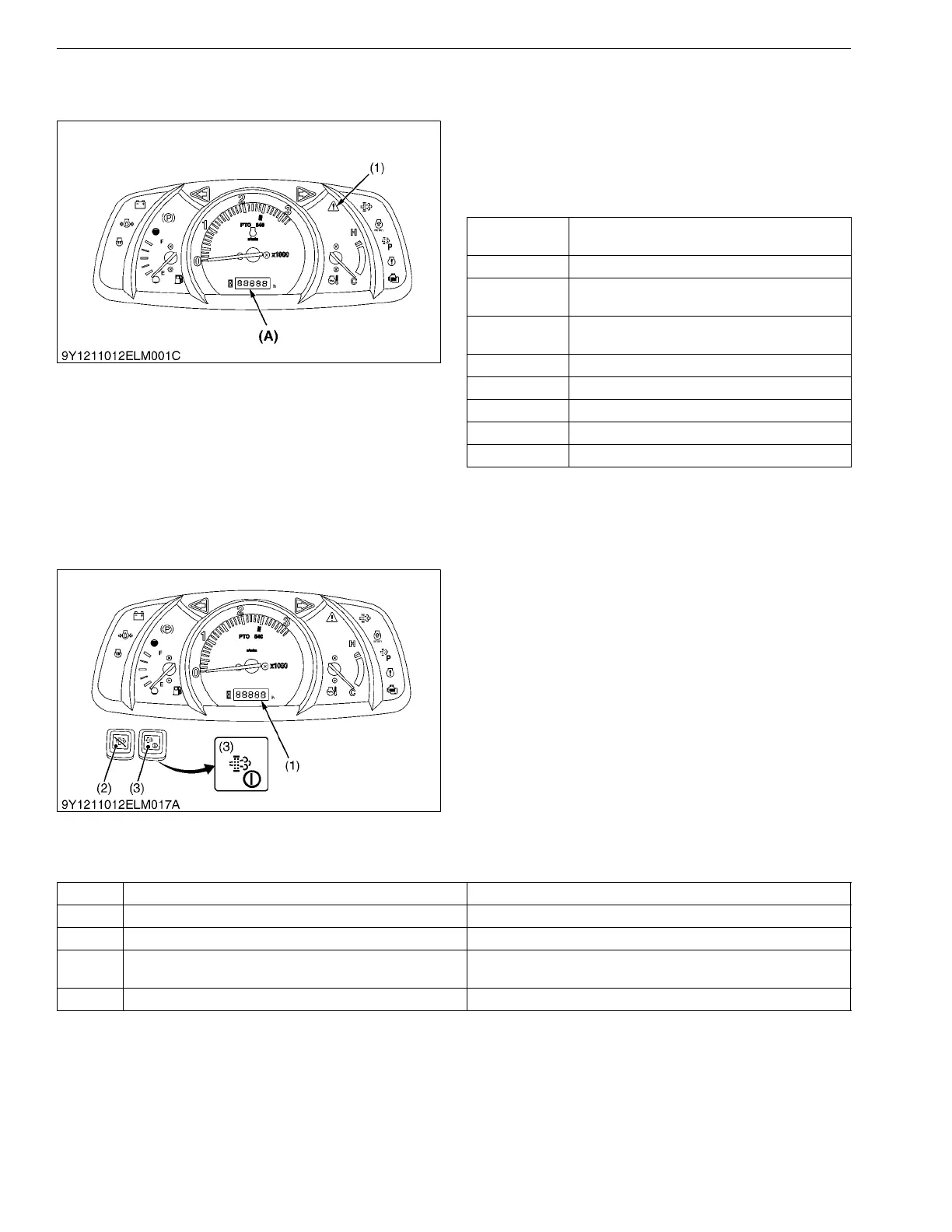
(1) Self-diagnosis Function
When the instrumental panel detects something
wrong, the master system warning indicator (1) starts
blinking and the error code indicating the location of the
trouble. showed in below is displayed on the liquid
crystal display.
9Y1211012ELM0029US0
(2) Testing, Setting and Adjusting Function
The instrumental panel can do various settings,
adjustments and testing by using the Liquid Crystal
Display (LCD) (1).
When the main switch is turned to "ON" or "START"
position while holding down the DPF INHIBIT switch (2)
and the parked regeneration switch (3) together, the
service inspect display is indicated. And then, a target
mode is selected, the data input and the fine adjustment,
etc. can be done. To select target mode, press the
parked regeneration switch (3) and the displayed mode
is changed. To decide, press the parked regeneration
switch (3) for few second while target mode is displayed.
The following table shows the content of each mode
display by the alphabet.
9Y1211012ELM0030US0
Displayed
error code
Trouble
E-20 Communication trouble
E-31
Meter's part code and ECU model setting not
compatible
E-40
Input voltage of lever sensor from ECU is in
trouble.
E-75 Acceleration sensor output out of spec
E-84 Acceleration sensor maladjusted
E-93 Relay for engine starter motor is in trouble
E-94 Relay for engine stop is in trouble
E-95 Solenoid (PTO) is in trouble
(1) Master System Warning
Indicator
(A) The error message is
displayed here.
(1) Liquid Crystal Display
(2) DPF INHIBIT Switch
(3) Parked Regeneration Switch
Mode Details of Mode Contents
A Test Mode For the checking the voltages from various sensors
b Error Information Clear Mode For the deleting the error information after servicing is finished
c Acceleration Sensor Fine-adjustment Mode
For setting the position of acceleration sensor
(Input the sensor information to main ECU)
d Tractor Model Select Mode For inputting the model of tractor to ECU