The
POLR
instruction also resets
and
clears
this
unit's
Processor
Fault
Interrupt signal and
the
error status
regis-
ter.
In
addition
to
the
operation
code
of
X'4F',
bits 15,
16,
and
17
must be
coded
as 011 ,
respectively.
Affected: (R),
CC1,
CC2,
CC3
Condition
code
settings for
the
POLR
instruction
are:
2 3 4 Result of
POLR
o 0 0 - Processor
fault
interrupt not pending.
o
AID
o - Processor
fault
interrupt pending.
o - Unit address not
recognized.
ACKNOWLEDGE INPUT/OUTPUT
INTERRUPT
(Word
index
alignment,
privileged)
ACKNOWLEDGE INPUT/OUTPUT
INTERRUPT
is used
to
acknowledge
an
input/output
interrupt and
to
identify the
I/O
subsystem (processor,
device
controller,
device)
that
is causing
the
interrupt and why.
If
more
than
one
I/o
subsystem has
an
interrupt pending, only
the
subsystem
with
the
highest priority will respond to
the
AIO.
Bits
18-
23 of
the
effective
virtual address of
the
AIO
instruction
(normally used to specify the cluster and
unit
addresses
of
the
I/O
address field) must be
coded
000000
to
specify
the
standard
I/O
system interrupt acknowledgment (other
codings of
these
bits
are
reserved for use with special
I/O
systems). The remainder of
the
I/o
selection
code
field
(bit positions 24-31)
are
not used in the standard
I/O
in-
terrupt acknowledgment (the address of
the
interrupt source
is a
part
of
the
response
from
the
standard
I/O
system to
the
AIO
instruction).
Standard
I/O
interrupts
are
program
controlled
via
the
con-
trol flags (IZC, ICE, IUE,
HTE,
and
SIL)
within
the
I/o
command doublewords (lOCOs)
that
comprise
the
command
list for
the
I/o
operation.
If
a
particular
flag is
coded
as
a 1
and
if
the
corresponding
condition
occurs within
the
I/O
operation,
then
an
I/O
interrupt is requested (e. g. ,
if
the IZC flag is set
to
1 and
if
the
byte
count
for
the
I/O
operation
has been decremented
to
zero,
then
an
I/O
interrupt is requested
by
that
I/o
subsystem to
indicate
the
end of
that
I/O
operation;
if
the
IZC flag is
coded
as a
0,
no
I/O
interrupt
is requested as a result of
the
byte
count
bei ng
decremented
to
zero).
If
two
or more
flags
are
coded
to
ClJuse
lJn
!nterrupt
for
two
or more
conditions,
an
interrupt
is
requested whenever
any
of
the
IIflagged
ll
conditions is
detected.
For some conditions (transmission errors,
incorrect
length),
two or more flags must be properly coded (see Chapter 4
for further
details
on
lOCOs).
140
Input/Output
Instructions
Some error conditi ons (e.
g.,
parity error on reading command
doubleword)
will unconditionally
cause
an
I/O
interrupt.
The various conditions which may result in
an
I/O
inter-
rupt,
the
coding of
the
corresponding control flags within
the
lOCO,
and
the
bit
position within
the
status word
(re-
turned
to
register
R)
that
indicates
the
presence
(1)
or
ab-
sence
(0) of
that
interrupt
condition
are
listed below:
Condition
Zero
byte
count
Channel end
T~ansmission
memory error
Write
lock
violation
Incorrect
length
Memory address error
I
lOP
memory error,
lOP
control error, or
device
connection
address
parity
error
T ransm i
ssi
on
data
error
Unusual end
lOP
halt
Control Flags
Coding
IZC = 1
ICE
= 1
IUE
= 1,
HTE
= 1
IUE
=
1,
HTE
= 1
IUE
=
1,
HTE
= 1
and
SIL
= 0
) (no flag
needed)
IUE=l,HTE=l
IUE
= 1
IUE
= 1
Status
Bit Set
10
11
12
12
8,
12
12
9,
12
12
12,
14
Interrupts may also be requested by
certain
I/O
devices
when they
execute
specific
orders (e.
g.,
when a magnetic
tape
unit
executes
a Rewind
and
Interrupt order). Refer
to
the
applicable
peripheral
reference
manual for further
details.
When a
device
interrupt
condition
occurs,
the
lOP
forwards
the
request
to
the interrupt system
I/o
interrupt
level.
If
this
interrupt
level is armed:
enabled:
and
not
inhibited;
the
BP
eventually
acknowledges the interrupt request and
executes
the
XPSD
instruction in main memory
location
X
'
5C',
which normally leads to
the
execution
of
an
AIO
i nstructi on.
For the purpose of acknowledging standard
I/O
interrupts,
the
lOPs,
device
controllers,
and
devices
are
connected
in
a preestablished priority sequence
that
is customer-assigned
and is
independent
of
the physical locations
of
the portions
of the
I/o
system in a
particular
installation.
If
the
R
field
of
the
AIO instruction
is
0,
the condition
code
;s set but the genera!
iegistsi
is
not
affected.
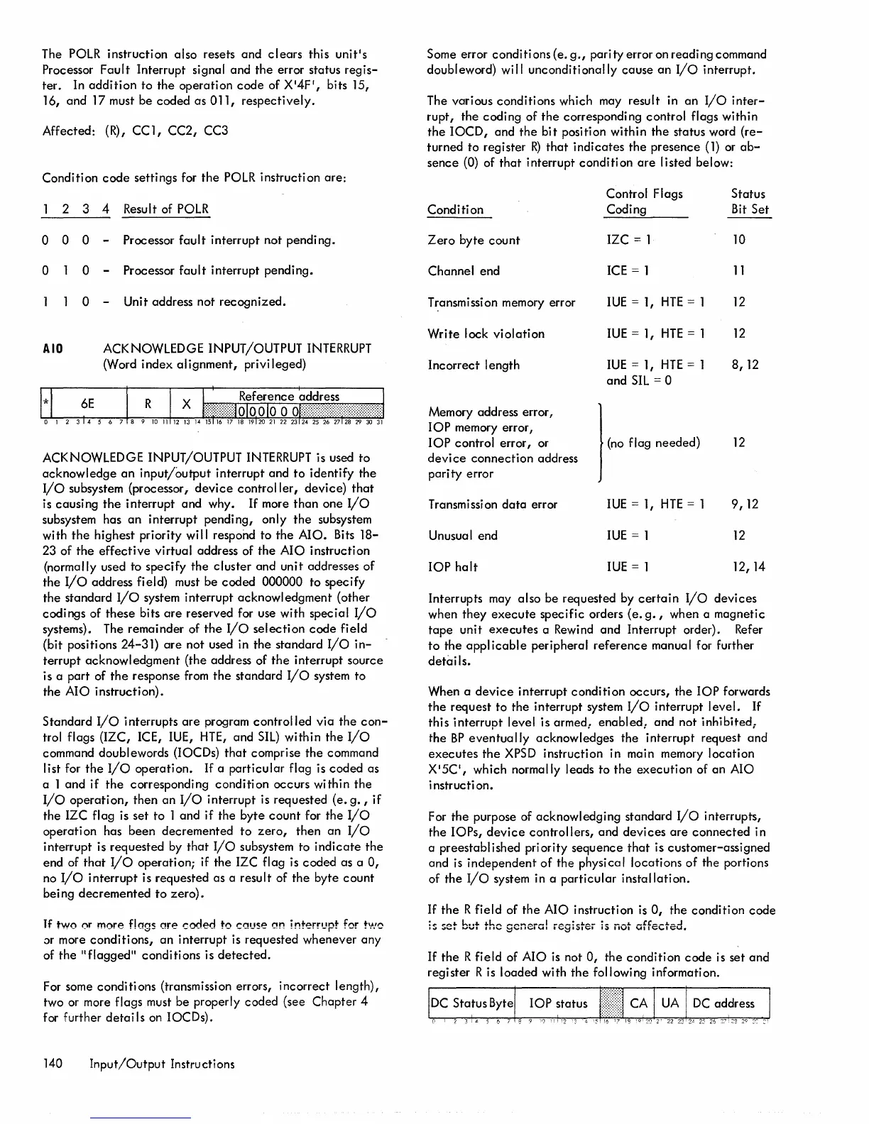
If
the
R field of AIO
is
not
0,
the
condition
code
is set
and
register R is loaded with
the
following information.

 Loading...


