7/98
Xerox DocuPrint P8e Service Manual 4-3 Repair Procedures
4.0 Overview
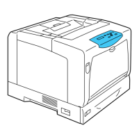
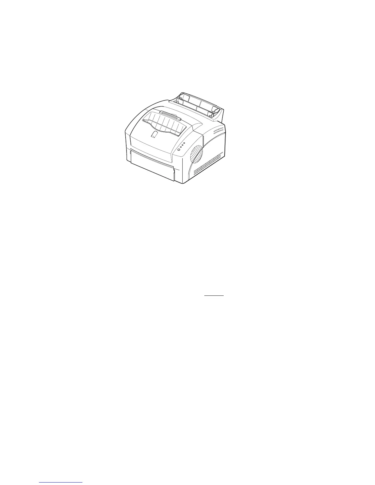
Locations given in the Repair Procedures are always referenced from the front of the printer as you are
facing the Control Panel. See figure 4.0.1.
Figure 4.0.1 Printer Orientation.
The following notations apply:
• Arrows in the illustrations show direction of movement.
• Numbers in an illustration refer to the corresponding steps in the procedure being performed.
Example, REP 4.1.1, step 2 indicates to press on the two locking tabs. Notice that the two locking
tabs in the illustration are labeled 2.
• At the bottom of each illustration is a number. In the illustration above the number is P8e_300. This
is the art number and is used by the developers for tracking and control of the art.
There are a number of steps you should follow each time before
you begin a procedure:
1 Do not use force to remove or install printer components.
2 Use only the screw size and type designated in the REP. The wrong screw could easily damage
tapped holes.
3 Wear a wrist strap to dissipate static electricity, which may damage sensitive electronic parts, and
use a grounded mat when working with PWBs.
4 See
Section 6
for the precise location of electrical connectors in the printer.
P8e_300
Front
Rear
Right
Left

 Loading...