MIPI CSI-2 RX Subsystem v4.0 12
PG232 July 02, 2019 www.xilinx.com
Chapter 1: Overview
AXI IIC
The Camera Control Interface (CCI) of the MIPI CSI-2 specification is compatible with the
fast mode variant of the I2C interface with 400 kHz operation and 7-bit slave addressing.
The AXI IIC is made available as part of this subsystem depending on user selections. See
the AXI IIC Bus Interface v2.0 LogiCORE IP Product Guide (PG090) [Ref 5] for details.
Applications
The Xilinx MIPI CSI-2 RX controller implements a Camera Serial Interface between a camera
sensor and a programmable device performing baseband processing. Bandwidth
requirement for the camera sensor interface has gone up due to the development of higher
resolution cameras. Traditional parallel interfaces require an increasing number of signal
lines resulting in higher power consumption. The new high speed serial interfaces, such as
MIPI CSI specifications, address these expanding bandwidth requirements without
sacrificing power. MIPI is a group of protocols defined by the mobile industry group to
standardize all interfaces within mobile platforms such as mobile phones and tablets.
However the large volumes and the economies of scale of the mobile industry is forcing
other applications to also adopt these standards. As such MIPI-based camera sensors are
being increasingly used in applications such as driver assistance technologies in automotive
applications, video security surveillance cameras, video conferencing and emerging
applications such as virtual and augmented reality.
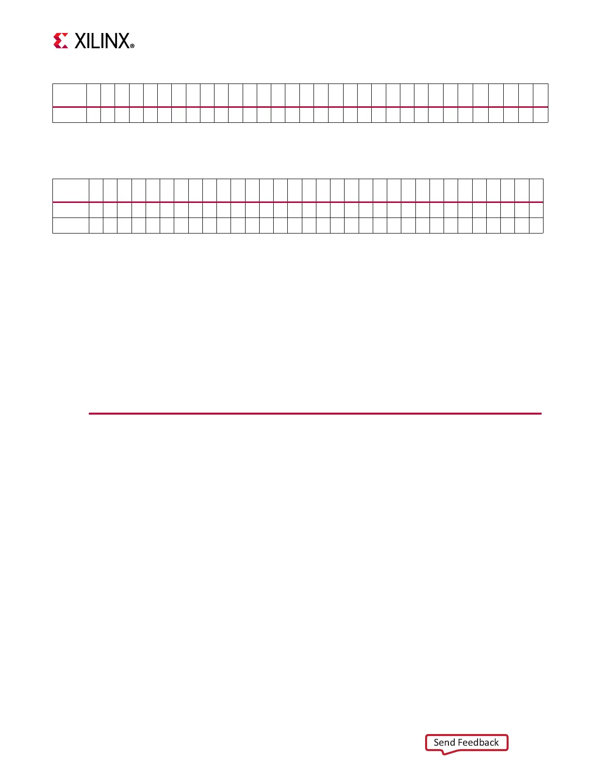
RAW10
y9 y8 y7 y6 y5 y4 y3 y2 x9 x8 x7 x6 x5 x4 x3 x2 w1 w0 v1 v0 u1 u0 t1 t0 w9 w8 w7 w6 w5 w4 w3 w2
Notes:
1. In RAW10, MSB 8-bits of 4 pixels are transferred first, followed by LSB 2-bits of each pixel.
Table 1-5: Pixel Packing for RAW10 Data Type
Bit
Position
31 30 29 28 27 26 25 24 23 22 21 20 19 18 17 16 15 14 13 12 11 10 9 8 7 6 5 4 3 2 1 0
Table 1-6: Pixel Packing for RGB888 Data Type
Bit
Position
313029282726252423222120191817161514131211109876543210
RGB888
d7 d6 d5 d4 d3 d2 d1 d0 c7 c6 c5 c4 c3 c2 c1 c0 b7 b6 b5 b4 b3 b2 b1 b0 a7 a6 a5 a4 a3 a2 a1 a0
RGB888
h7 h6 h5 h4 h3 h2 h1 h0 g7 g6 g5 g4 g3 g2 g1 g0 f7 f6 f5 f4 f3 f2 f1 f0 e7 e6 e5 e4 e3 e2 e1 e0
Notes:
1. In RGB888, a0 to a7 represents the B component, b0 to b7 represents the G component and c0 to c7 represents the R
component.
 Loading...