MIPI CSI-2 RX Subsystem v4.0 63
PG232 July 02, 2019 www.xilinx.com
Chapter 5
Application Example Design
This chapter contains step-by-step instructions for generating an MIPI CSI-2 Rx Subsystem
application example design from the MIPI CSI-2 Rx Subsystem by using the Vivado® flow.
Application Example Design Overview
The Application Example Design demonstrates the usage of the MIPI CSI-2 RX Subsystem
and MIPI DSI TX Subsystem on Zynq Ultra Scale+ ZCU102 board. On the capture path, the
system receives images captured by IMX274 image sensor. Processed images are displayed
on either the HDMI monitor or MIPI DSI Display.
A block diagram of the MIPI CSI-2 Rx Subsystem Application Example Design is shown in
Figure 5-1.
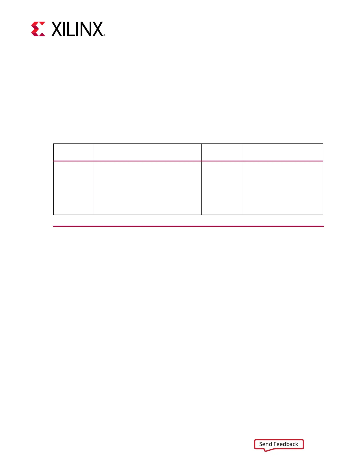
Table 5-1: Hardware Details of the Application Example Design
Topology Hardware Processor
Lanes, Line-rate, and Data
Type
MIPI Video
Pipe Camera
to Display
• ZCU102 Rev 1.0
• AUOS display panel (B101UAN01.7_H/
W 1A)
• LI-IMX274MIPI-FMC camera sensor
module
• HDMI monitor supporting 4K@30 fps
with at least 12 bpc color depth
Zynq®
MPSoC
4 Lanes,1440 Mb/s Lane,
RAW10
 Loading...