MIPI CSI-2 RX Subsystem v4.0 65
PG232 July 02, 2019 www.xilinx.com
Chapter 5: Application Example Design
Setup Details
This section lists the prerequisites and setup required for ZCU102 based application
example design.
Prerequisites
Prior to working on the rest of instructions in this section, ensure that you have the
following hardware available with you.
• Zynq® UltraScale+™ ZCU102 Rev 1.0 board and power supply
• JTAG USB Platform cable or USB cable Type A to micro - B
• USB cable Type A to micro-B for USB-UART
•HDMI cable
• HDMI Monitor supporting 4K@30 fps with at least 12 bpc color depth
• AUOS DSI Display panel (B101UAN01.7_H/W 1A) with ribbon cable
• LI-IMX274MIPI-FMC Camera sensor module
• Host PC (to program and communicate with the program via UART)
Hardware Setup
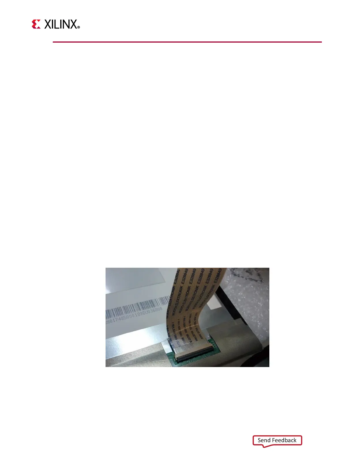
1. Connect the ribbon cable to the AUO display panel.
2. Connect the other end of the ribbon cable to the LI-IMX274MIPI-FMC Camera sensor
module.
X-Ref Target - Figure 5-2
Figure 5-2: Connect Ribbon Cable to AUO Display Panel
 Loading...