MIPI CSI-2 RX Subsystem v4.0 66
PG232 July 02, 2019 www.xilinx.com
Chapter 5: Application Example Design
3. Setup the hardware connections:
a. Mount the LI-IMX274MIPI-FMC Camera sensor module on the ZCU102 board HPC0
FMC Slot.
b. Connect the HDMI cable to the ZCU102 HDMI port (top port) (Figure 5-4).
c. Connect the other end of the HDMI cable to the HDMI monitor.
d. Switch on the HDMI monitor, and select HDMI as input source.
e. Connect USB-UART type A to micro USB cable from the host PC to the UART micro
USB port of board.
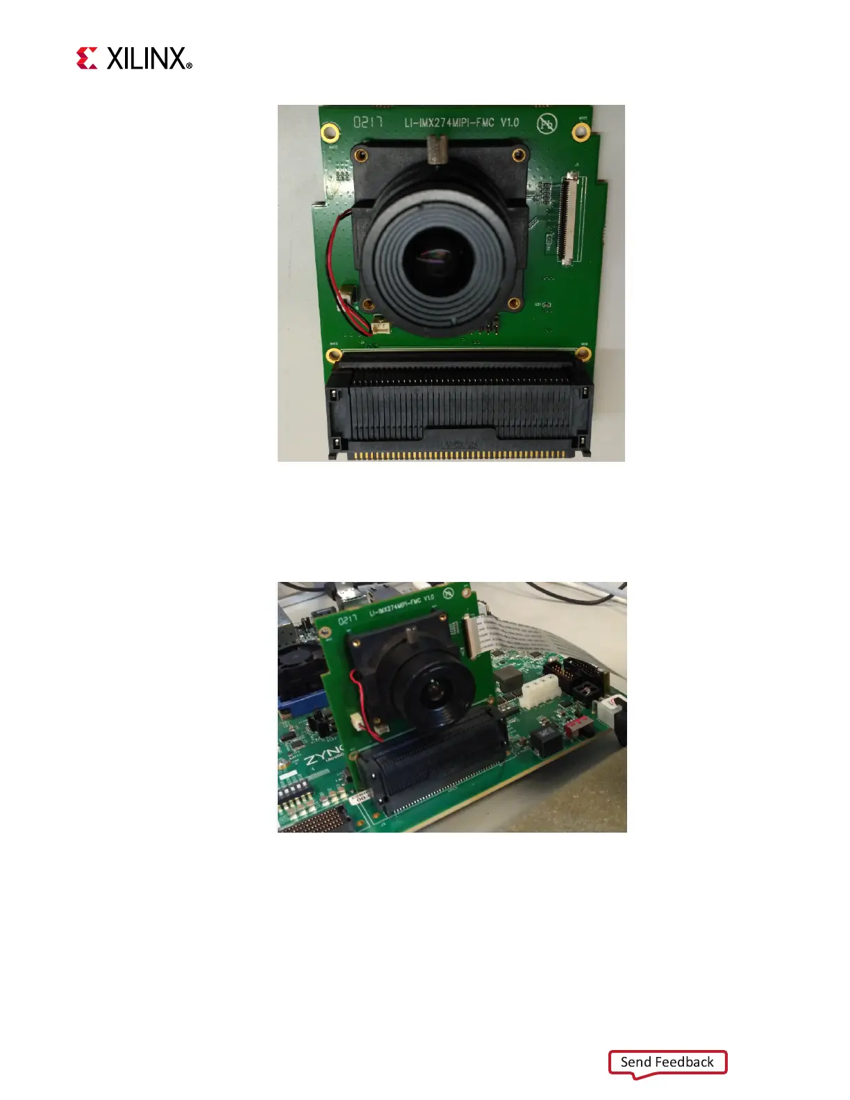
X-Ref Target - Figure 5-3
Figure 5-3: LI-IMX274MIPI-FMC Camera Sensor Module
X-Ref Target - Figure 5-4
Figure 5-4: LI-IMX274MIPI-FMC Camera Sensor Module
 Loading...