MIPI CSI-2 RX Subsystem v4.0 48
PG232 July 02, 2019 www.xilinx.com
Chapter 3: Designing with the Subsystem
Note: The effect of each reset (lite_resetn, video_aresetn) is determined by the ports of the
sub-cores to which they are connected. See the individual sub-core product guides for the effect of
each reset signal.
Protocol Description
Programming Sequence
This section contains the programming sequence for the subsystem. Program and enable
the components of subsystem in the following order:
1. AXI IIC (if included)
2. MIPI CSI-2 RX Controller
3. MIPI D-PHY (if register interface is enabled)
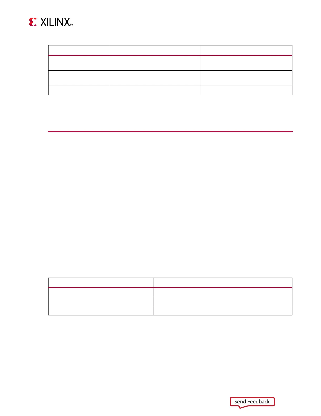
Address Map Example
Tab l e 3 - 4 shows an example based on a subsystem base address of 0x44A0_0000 (32-bits)
when the AXI IIC core is included and the MIPI D-PHY register interface is enabled.
AXI IIC IP Core Programming
See the AXI IIC Bus Interface v2.0 LogiCORE IP Product Guide (PG090) [Ref 5] for AXI IIC IP
core programming details.
Video Format Bridge N/A
Connected to
s_axis_aresetn
core
port
AXI IIC
Connected to s_axi_aresetn core
port
N/A
AXI Crossbar Connected to aresetn core port N/A
Table 3-4: Address Map Example
Core Base Address
MIPI CSI-2 RX Controller 0x44A0_0000
AXI IIC 0x44A1_0000
MIPI D-PHY 0x44A2_0000
(1)
Notes:
1. When the AXI IIC IP core is not present and the MIPI D-PHY register interface is enabled, the base address of the
MIPI D-PHY starts with 0x44A1_0000.
Table 3-3: Resets (Cont’d)
Sub-core Lite_aresetn Video_aresetn
 Loading...