MIPI CSI-2 RX Subsystem v4.0 16
PG232 July 02, 2019 www.xilinx.com
Chapter 2: Product Specification
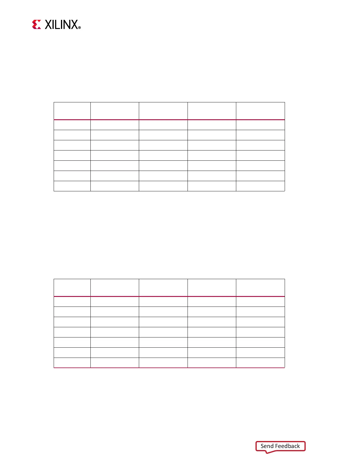
MIPI CSI-2 RX Controller latency:
The MIPI CSI-2 RX Controller core latency is the time from the activehs assertion on the PPI
Interface to valid signal assertion on the controller output.
Tab l e 2 - 2 provides the latency numbers for various core configurations.
Video Format Bridge (VFB) latency:
The VFB core latency is the time time from the VFB input stream interface ‘tvalid’ to VFB
output stream interface ‘tvalid’.
Tab l e 2 - 3 provides the latency numbers for various core configurations.
Table 2-2: MIPI CSI2 RX Controller latency
Data Type Pixel Mode Line Rate
Latency in
rxbyteclk
Latency in Video
Clock
RAW20 Single
1000 25 60
RAW8 Single
1000 21 49
RAW8 Dual
1000 21 49
RAW8 Quad
1000 21 49
RAW10 Single
1000 25 60
RAW10 Dual
1200 26 63
RAW10 Quad
800 24 56
Notes: All the calculations are made for a single lane design with a fixed video clock of 148
MHz.
Table 2-3: VFB latency
Data Type Pixel Mode Line Rate
Latency in
rxbyteclk
Latency in Video
Clock
RAW20 Single
1000 10 24
RAW8 Single
1000 1 3
RAW8 Dual
1000 1 3
RAW8 Quad
1000 1 4
RAW10 Single
1000 2 6
RAW10 Dual
1200 3 6
RAW10 Quad
800 1 3
Notes: All the calculations are made for a fixed video clock of 148 MHz.
 Loading...