ZCU106 Board User Guide 115
UG1244 (v1.0) March 28, 2018 www.xilinx.com
Chapter 3: Board Component Descriptions
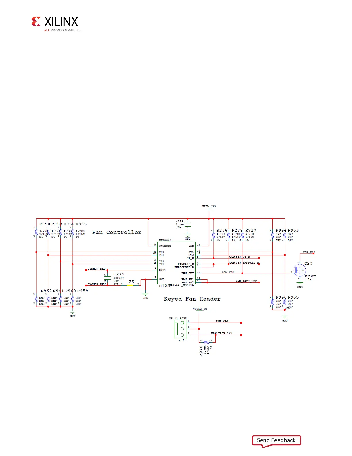
Cooling Fan Connector
[Figure 2-1, near callout 10]
The ZCU106 cooling fan connector is shown in Figure 3-43.
The ZCU106 uses the Maxim MAX6643 fan controller, which autonomously controls the fan
speed by controlling the pulse width modulation (PWM) signal to the fan based on the die
temperature sensed via the FPGA's DXP and DXN pins. The fan rotates slowly (acoustically
quiet) when the FPGA is cool and rotates faster as the FPGA heats up (acoustically noisy).
The fan speed (PWM) versus the FPGA die temperature algorithm along with the over
temperature set point and fan failure alarm mechanisms are defined by the strapping
resistors on the MAX6643 device. The over temperature and fan failures alarms can be
monitored by the any available processor in the FPGA by polling the I2C expander, U97. See
the MAX6643 [Ref 22] data sheet for more information on the device circuit implementation
on this board.
Note:
At initial power on, it is normal for the fan controller to energize at full speed for a few
seconds.
X-Ref Target - Figure 3-43
Figure 3-43: ZCU106 12V Fan Controller