ZCU106 Board User Guide 68
UG1244 (v1.0) March 28, 2018 www.xilinx.com
Chapter 3: Board Component Descriptions
GPIO (MIO 22-23)
PS-side pushbutton SW19 is connected to MIO22 (pin U1.F28). PS-side LED DS50, physically
placed adjacent to the pushbutton, is connected to MIO23 (pin U1.B29).
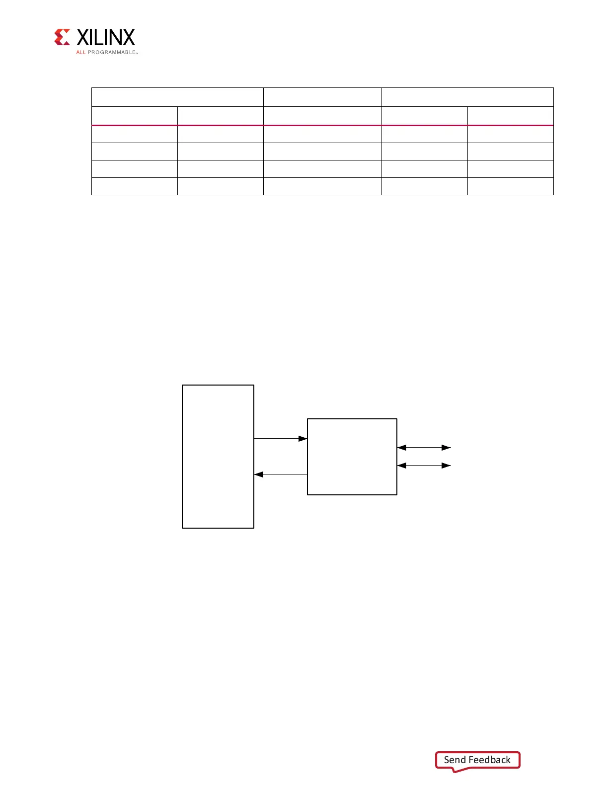
CAN1 (MIO 24-25)
The PS-side CAN bus TX and RX MIO nets are wired through TXS0104E level-translator U33
and TI SN65HVD232 CAN-bus transceiver U122 to the 0.1 inch pitch 8-pin male header J98
(see Figure 3-20 and Figure 3-21).
Table 3-26: XCZU7EV U1 PS-Side to CP2108 U40 Connections via L/S U54
XCZU7EV U1 Net Name CP2108 U40
Pin Name Pin # Net Name Pin Name Pin #
PS_MIO18 F27 MIO18_UART0_RXD TX_0 57
PS_MIO19 B28 MIO19_UART0_TXD RX_0 56
PS_MIO21 C28 MIO21_UART1_RXD TX_1 49
PS_MIO20 E29 MIO20_UART1_TXD RX_1 48
X-Ref Target - Figure 3-20
Figure 3-20: PS-Side CAN Bus Interface Diagram
TXS0104E
SN65HVD232
CANH
CANL
CAN_TX
CAN_RX
X16533-050117