ZCU106 Board User Guide 42
UG1244 (v1.0) March 28, 2018 www.xilinx.com
Chapter 3: Board Component Descriptions
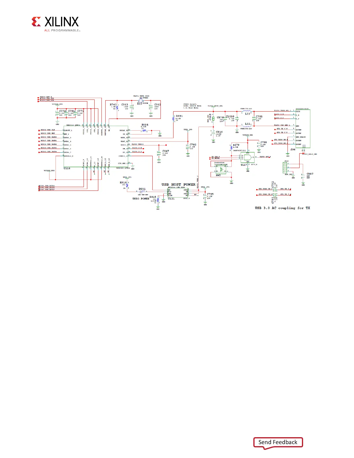
The USB3320 ULPI U116 transceiver circuit (see Figure 3-4) has a Micrel MIC2544 high-side
programmable current limit switch (U121). This switch has an open-drain output fault flag
on pin 2, which turns on LED DS51 if over current or thermal shutdown conditions are
detected. DS51 is located in the U116 circuit area near pushbutton SW2 (Figure 2-1, callout
5).
SD1 (MIO 39-51)
A PS-side interface to an SD card connector is provided for booting and file system storage.
This interface is used for the SD boot mode and supports SD3.0 access post boot.
SD Card Interface
[Figure 2-1, callout 6]
The ZCU106 board includes a secure digital input/output (SDIO) interface to provide access
to general purpose non-volatile SDIO memory cards and peripherals. See the SanDisk
Corporation [Ref 17] or SD Association [Ref 18] websites for more information on the SD
I/O card specification. The ZCU106 SD card interface supports the SD1_LS configuration
boot mode documented in the Zynq UltraScale+ MPSoC Technical Reference Manual
(UG1085) [Ref 2].
The SDIO signals are connected to XCZU7EV MPSoC PS bank 501, which has its V
CCMIO
set to
1.8V. Each of the six MIO[46-51]_SDIO_* nets has a series 30Ω resistor at the source. An NXP
IP4856CX25 SD 3.0-compliant voltage level-translator U133 is present between the
XCZU7EV MPSoC and the SD card connector (J100). The NXP IP4856CX25 U133 device
provides SD3.0 capability with SDR104 performance.
X-Ref Target - Figure 3-4
Figure 3-4: ULPI U116 Transceiver Circuit

 Loading...


