ZCU106 Board User Guide 71
UG1244 (v1.0) March 28, 2018 www.xilinx.com
Chapter 3: Board Component Descriptions
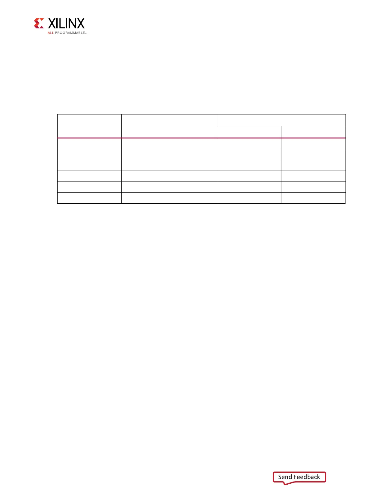
PMU GPO (MIO 32-37)
The PMU within the Zynq UltraScale+ MPSoC signals power domain changes using the PMU
output pins for deep-sleep mode. The Zynq UltraScale+ MPSoC PMU GPO pins are
connected to inputs of the MSP430 system controller via TXS0108E level-shifter U141. The
connections from MPSoC U1 bank 501 to MSP430 U41 are listed in Table 3-28.
Through the I2C0 bus MPSoC MIO pins, the PMU has access to the board power controllers
and power monitors. See Figure 3-17, page 61 for more details.
See the Zynq UltraScale+ MPSoC Technical Reference Manual (UG1085) [Ref 2] for more
details about the PMU interface.
HDMI Video Output
[Figure 2-1, callout 14]
The ZCU106 board provides an HDMI® video output using a TI SN65DP159RGZ re-timer at
U94. The output is provided on a TE Connectivity 1888811-1 right-angle dual-stacked HDMI
type-A receptacle at P7. The SN65DP159RGZ device is a dual mode DisplayPort to
transition-minimized differential signal (TMDS) re-timer supporting digital video interface
(DVI) 1.0, HDMI 1.4b, and 2.0 output signals.
The SN65DP159RGZ device supports the dual mode standard version 1.1 type 1 and type 2
through the digital down converter (DDC) link or AUX channel. The SN65DP159RGZ device
supports data rates up to 6 Gb/s per data lane to support Ultra HD (4K x 2K/60 Hz) 8-bits
per color high-resolution video and HDTV with 16-bit color depth at 1080p
(1920 x 1080/60 Hz). The SN65DP159RGZ device can automatically configure itself as a
re-driver at data rates <1 Gb/s, or as a re-timer at more than this data rate. This feature can
be turned off with I2C programming.
Table 3-28: XCZU7EV U1 to MSP430 Connections
XCZU7EV (U1) Pin Net Name
MSP430 U41
Pin Name Pin #
C33 MIO37_PMU_GPO5 P1_0 13
C32 MIO36_PMU_GPO4 P1_1 14
C31 MIO35_PMU_GPO3 P1_2 15
B34 MIO34_PMU_GPO2 P1_3 16
B33 MIO33_PMU_GPO1 P1_4 17
B31 MIO32_PMU_GPO0 P1_5 18