ZCU106 Board User Guide 72
UG1244 (v1.0) March 28, 2018 www.xilinx.com
Chapter 3: Board Component Descriptions
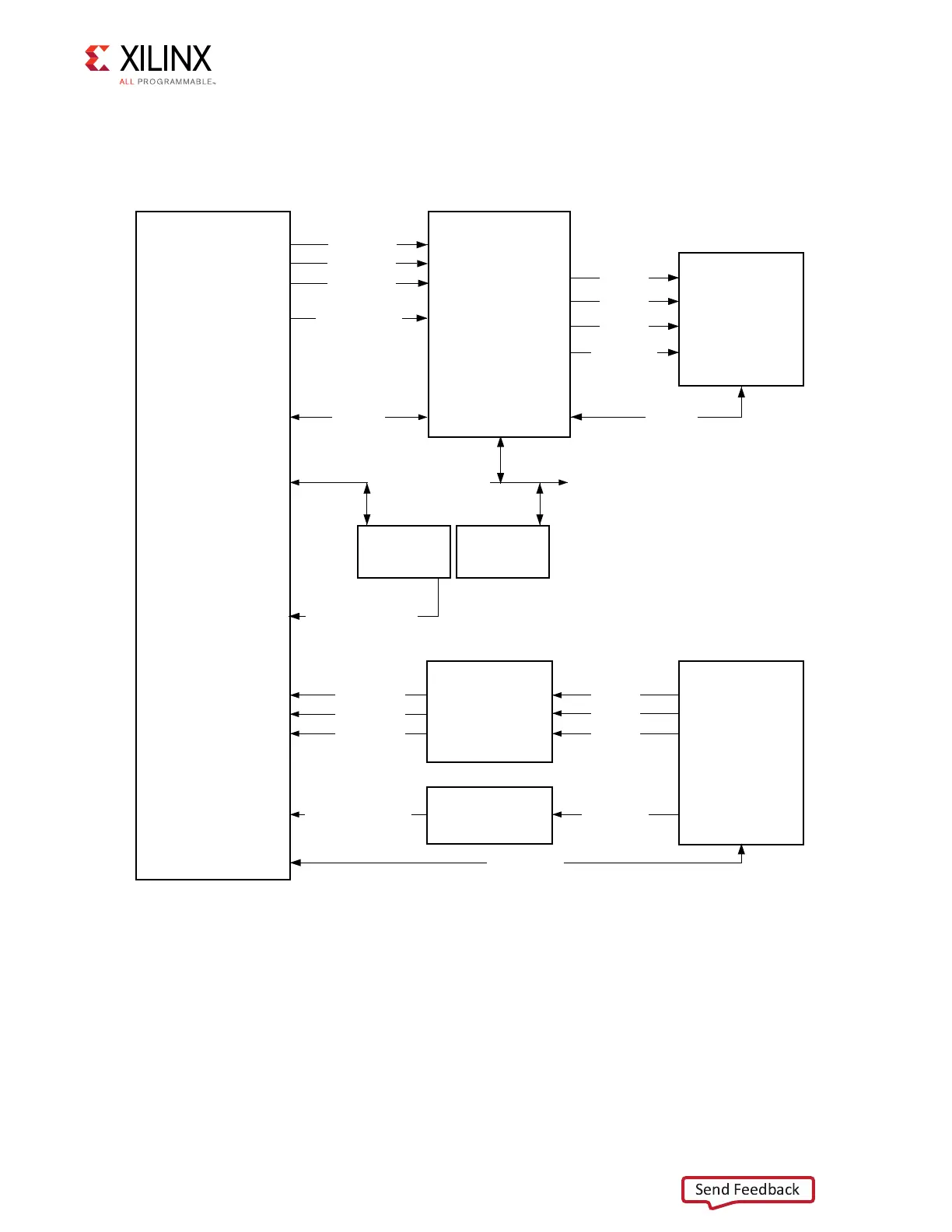
The HDMI block diagram, the TX interface circuit, and the RX interface circuit are shown in
Figure 3-23, Figure 3-24, and Figure 3-25, respectively. The XCZU7EV MPSoC U1 to HDMI
circuit connections are listed in Table 3-29.
X-Ref Target - Figure 3-23
Figure 3-23: HDMI Interface Block Diagram
Driver
(SN65DP159)
HDMI_TX_1
HDMI_TX_2
TX_CLK_LVDS
I2C_SRC
I2C_CTL_HDMI_OUT
S15324
EDID
EEPROM
TMDS181
Retimer
CLK Buffer
HDMI_IN
P7 Bottom
HDMI_OUT
P7 Top
TMDS_0
TMDS_1
TMDS_2
TMDS_CLK
I2C_SNK
TX_GTH_REF_CLK
HDMI_RX_0
HDMI_RX_1
HDMI_RX_2
RX_GTH_REFCLK
TMDS_0
TMDS_1
TMDS_2
TMDS_CLK
I2C_HDMI_IN
HDMI_TX_0
GTH223 TX
BANK28 GC
PL-Side
HDMI
IP
BANK67
HDMI_REC_CLOCK
GTH223
REFCLK0
GTH223 RX
GTH223
REFCLK1
X19188-052417