120
6.2.4 Operation steps
Estimate the inertia through the driver panel
1. Parameter setting
Inertia identification
and internal
instruction
auto-tuning max
speed
Inertia identification
initial inertia ratio
The recommended parameters of P2-17 are 500 rpm or more. Low instruction speed will lead to
inaccurate identification of inertia ratio.
2. Execute the inertia identification
Before inertia identification, please confirm the direction of servo rotation by using F1-00 jog motion
function. Initial direction of servo operation is determined by INC or DEC at the beginning of inertia
identification.
If the servo jitter is under the adaptive default parameters, please switch to the adaptive large inertia
mode (P2-03.3=1) to ensure the basic smooth operation of the servo and then identify the inertia!
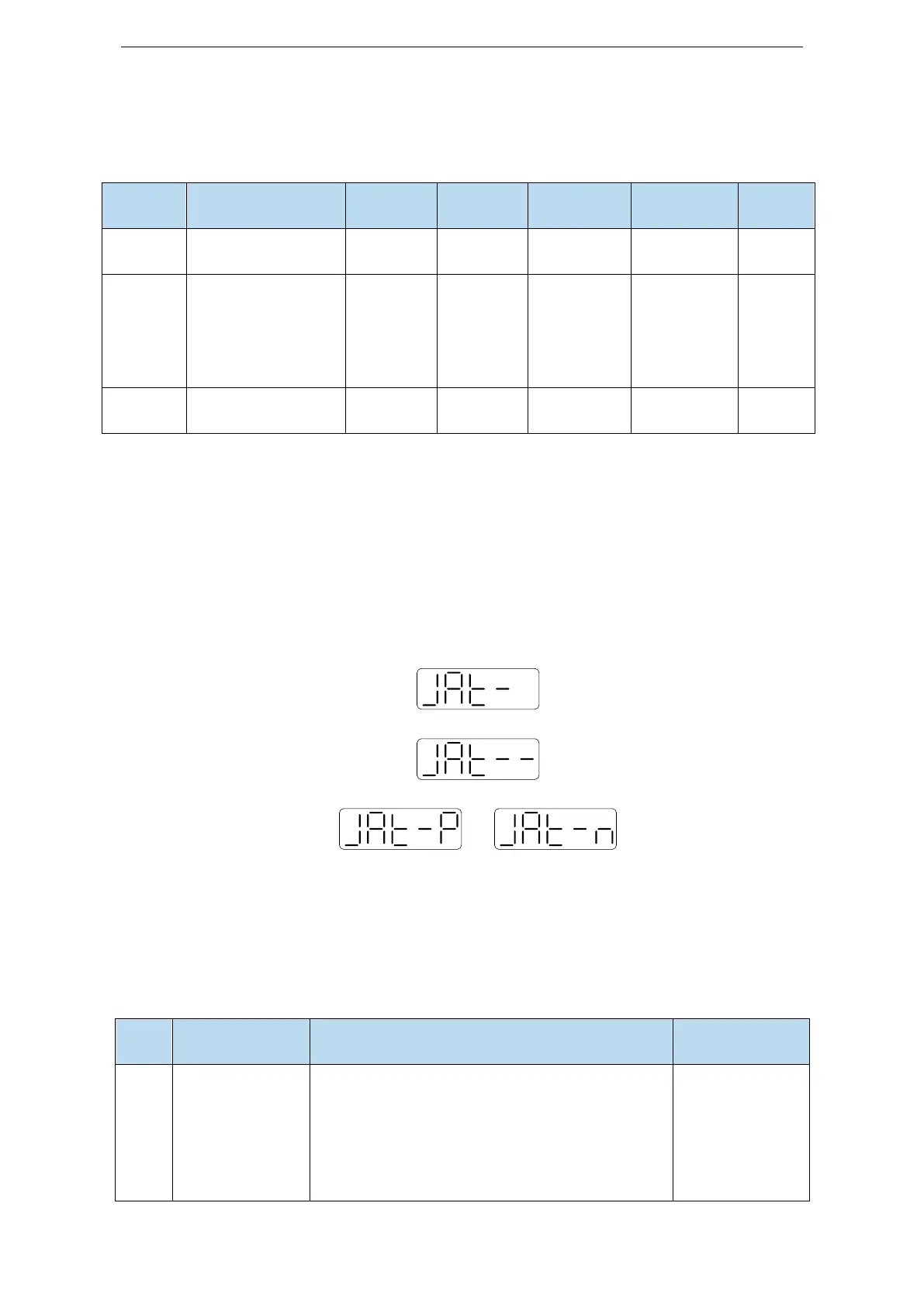
Servo entering parameter F0-07 in BB state:
Press ENTER, servo is enabled:
Press INC or DEC to run forward or reverse (select one of them):
or
At this point, start action, under the condition of P-05 = 0 (initial positive direction), if press INC, then
turn forward and then reverse; if press DEC, turn reverse and then forward. If the inertia identification
is successful, the load inertia ratio is prompted and written to P0-07 automatically after several forward
and reverse operations. If the inertia identification error occurs, the error code will be displayed. Press
STA/ESC key to exit the panel inertia identification operation.
Alarm for inertia identification of panel
① Initial inertia is too small; in adaptive mode,
switch to large inertia mode P2-03.3=1 or the initial
inertia of inertia identification P2-18 set to 2 times
of the present value.
② The maximum speed is too high (P2-17), but it is
recommended not to be less than 500 rpm. Low
Initial inertia too
small; Maximum
speed too large;
Torque limit too
small
 Loading...
