146
Note: for above each step, press STA/ESC can return to the last step or exit.
6.7.7 Notch filter
Notch filter can suppress mechanical resonance by reducing the gain at a specific frequency. After the
notch filter is set correctly, the vibration can be effectively suppressed and the servo gain can be
continuously increased.
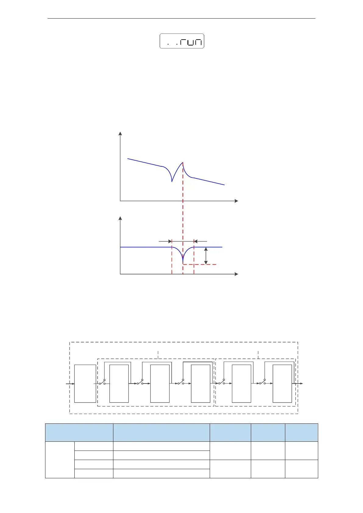
The principle diagram of notch filter is as follows:
Mechanical resonance
frequency
mechanical system
Amplitude frequency
characteristic
Notch
characteristics
Notch
width
Notch
depth
frequency
frequency
Principle diagram of notch filter
The servo driver has five sets of notch filters, each with three parameters, notch frequency, notch
attenuation and notch bandwidth. The first and second notches are set automatically, and the third,
fourth and fifth are set manually.
The torque instruction filter and notch filter are in series in the system. As shown in the figure below,
the switch of the notch filter is controlled by P2-69 and P2-70.
Torque
command
filter
P2-35
First
notch
filter
P2-71
P2-72
P2-73
Second
notch
filter
P2-74
P2-75
P2-76
Third
notch
filter
P2-77
P2-78
P2-79
Fourth
notch
filter
P2-80
P2-81
P2-82
Fifth
notch
filter
P2-83
P2-84
P2-85
Torque
instruction
after filter
Torque
instruction
before
filter
P2-69
control
P2-70
control
 Loading...
