37
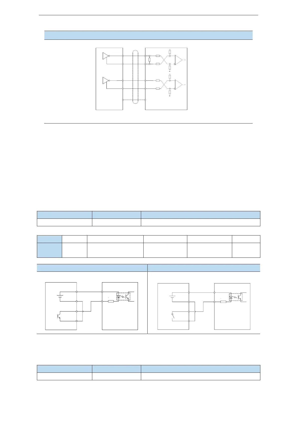
Line driver pulse wiring method
PLC, CNC, SCM servo driver
HP-
HP+
GND
120Ω
2KΩ
2KΩ
HD-
HD+
2KΩ
2KΩ
10KΩ
10KΩ
10KΩ
10KΩ
GND
Note: In order to resist interference, twisted-pair shielding wire must be used.
Note:
(1) The power supply voltage range of P- / P+ 24V and D- / D+ 24V is 18V ~ 25V. The power
supply voltage range of P- / P+ 5V and D- / D+ 5V is 3.3V ~ 5V. If it is lower than 18V / 3.3V, there
may be abnormal pulse and direction.
(2) Servo pulse input port is ON for 10mA.
(3) If the controller is Xinje PLC, the rated current of the pulse output port is 50mA. According to
this data, it can be judged that one pulse theoretically can drive at most five servos. It is recommended
not to exceed 3.
3.2.2 SI input signal
Please use a relay or an open collector transistor circuit to connect. When using relay connection,
please select the relay for small current. If the relay is not small current, it will cause bad contact.
Multifunctional input signal terminal
Defaulted assignment of input terminals
P-OT/forward run
prohibition
N-OT/reverse run
prohibition
Open collector (power supply is 24V)
Relay type (power supply is 24V)
Upper device servo driver
SI
+24V
+
COM2
Y2
0V
+24V
R=3.3KΩ
Upper device servo driver
R=3.3KΩ
+24V
0V
Y2
COM2
+
+24V
SI
Note: SI10 terminal is high-speed input port, and SI1-SI9 are low-speed input ports.
3.2.3 SO output signal
Multifunctional output terminal
Note:
(1) It is suggested
to add the
differential
isolation board of
Xinje;
(2) CW/CCW pulse
input frequency is
2M at most, and
AB phase pulse
frequency is 2M at
most.
 Loading...
