14 BiSS
YASKAWA TOEPC710616134G AC Drive L1000A Technical Manual Addendum 93
Table 14.1 PG Encoder Cable Specification
Option Terminal
PG Encoder Cable
Color
*1
PG Encoder Signal
*2
IP
Brown/Green Up
Blue Sensor Up
IG
White/Green 0 V
White Sensor 0 V
CK Purple CLOCK
/CK Yellow /CLOCK
DT Gray DATA
/DT Pink /DATA
A+ Green/Black A+
A- Yellow/Black A-
B+ Blue/Black B+
B- Red/Black B-
*1 Colors depend on the manufacturer. Check the data sheet of the encoder cable for the actual colors.
*2 Signal names depend on the manufacturer. Check the data sheet of the encoder cable for the signal names.
Wire Gauges, Tightening Torques
Use the following wire gauges and torques.
Terminal Signal Screw Size
Tightening
Torque
Nm (in·lb)
Bare Cable Crimp Terminals
Wire Type
Recommended
Gauge
mm
2
Applicable
Gauge
mm
2
Recommended
Gauge
mm
2
Applicable
Gauge
mm
2
a+, a-, b+, b-, FE
M2
0.22 to 0.25
(1.95 to 2.21)
0.75
(AWG 18)
Stranded wire:
0.25 to 1.0
(AWG 24 to 17)
Solid wire:
0.25 to 1.5
(AWG 24 to 16)
0.5
(AWG 20)
0.25 to 0.5
(AWG 24 to 20)
Shielded twisted
pair, etc.
IP, IG, DT, /DT,
B+, B-, CK, /CK, A
+, A-
*1
- - -
*1 Use an 8-pin cable. Refer to PG Encoder Cable Specification for details.
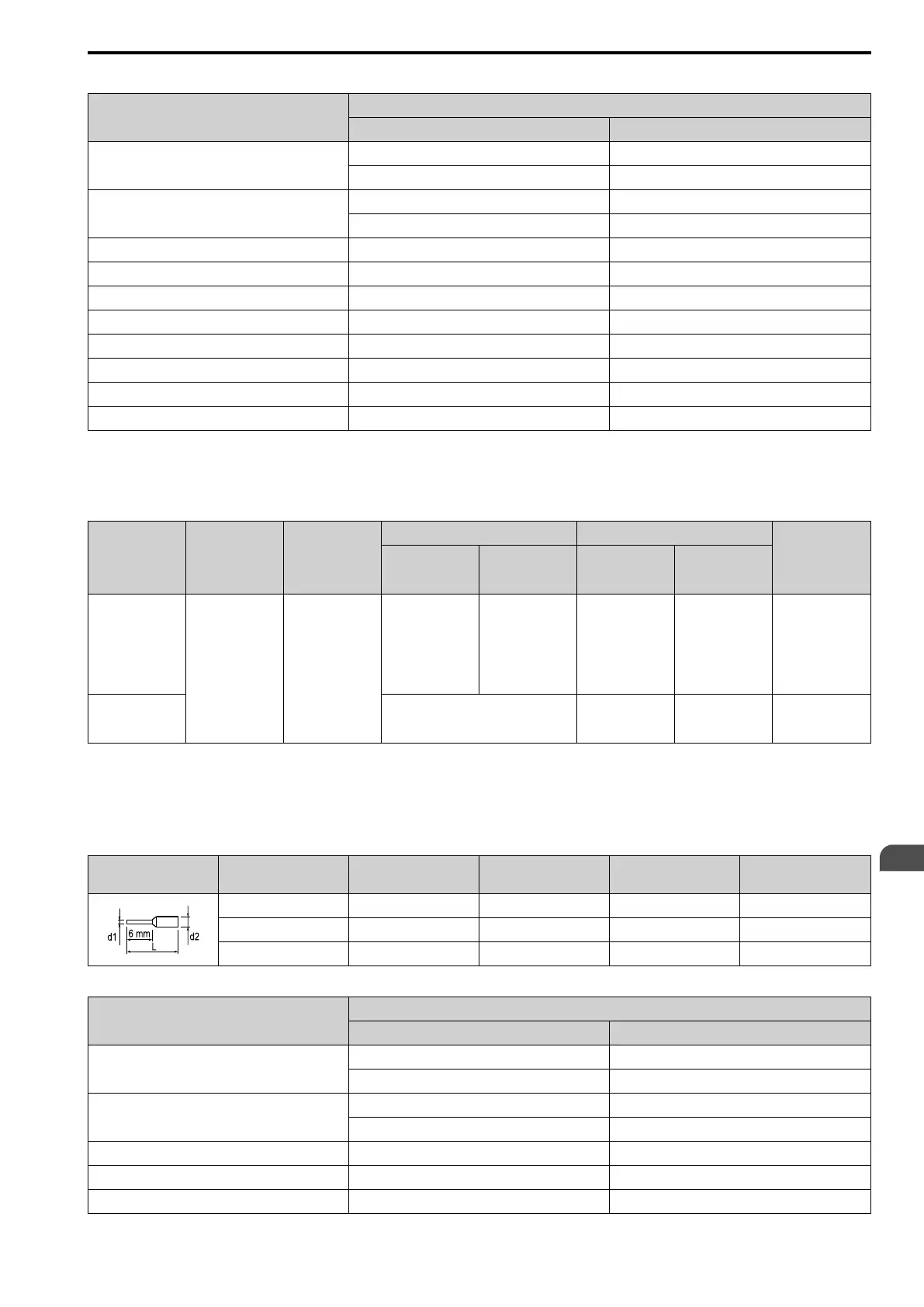
Crimp Terminals
Use a Phoenix Contact CRIMPFOX 6 or equivalent and crimp terminals with the following specifications for
wiring to ensure proper connections. Properly trim wire ends so loose wire ends do not extend from the crimp
terminals.
Wire Gauge
mm
2
Phoenix Contact Model
L
mm (in.)
d1
mm (in.)
d2
mm (in.)
0.25 (AWG 24) AI 0.25 - 6YE 10.5 (13/32) 0.8 (1/32) 2 (5/64)
0.34 (AWG 22) AI 0.34 - 6TQ 10.5 (13/32) 0.8 (1/32) 2 (5/64)
0.5 (AWG 20) AI 0.5 - 6WH 14 (9/16) 1.1 (3/64) 2.5 (3/32)
Example: Connecting the PG-F3 Option Card to Kübler Sendix 5853 or 5873 Encoder
Option Terminal
PG Encoder Cable
Color PG Encoder Signal
IP
Brown +V
Red/Blue +Vsens
IG
White 0 V
Gray/Pink +V
CK Green C+
/CK Yellow C-
DT Gray D+
EN

 Loading...


