EasyManuals Logo

YASKAWA SGDA series User Manual

YASKAWA SGDA series
429 pages
To Next Page IconTo Next Page
To Previous Page IconTo Previous Page
Page #400 background imageLoading...
Page #400 background image
391
Specifi-
cations
Speed Control
with Torque
Restriction by
Analog
Voltage
Reference
Contact Input Speed
Control
Zero-
clamp
Torque
Limit
Output
Absolute
Encoder
Standard
Specifications
Memory
Switch
Setting
Cn-02
Bit F = 1
Cn-02 Bit 2 = 1Cn-01
Bit A = 1
Bit B = 0
Cn-01
Bit 4 = 1
Cn-01
Bit E = 1
Standard SettingMemory
Switch
Setting
Cn-02
Bit F = 1
Cn-01
Bit B = 1
Cn-01
Bit B = 0
Cn-01
Bit A = 1
Bit B = 0
Cn-01
Bit 4 = 1
Cn-01
Bit E = 1
Standard Setting
13 +24VIN
I/O power supply
14 S-ON
Servo ON
15 P-CON
Proportional control
P-CON
Zero-clamp
operation
reference
P-CON
Rotation
direction
reference
P-CON
Rotation
direction
reference
16 P-OT
Forward rotation
prohibited
17 N-OT
Reverse rotation
prohibited
18 ALMRST
Alarm reset
19 SG-PG
Signal ground for PG
signal output
20 PAO
Phase A
PG signal
output
21 *PAO
Phase
A
output
22 PBO
Phase B
23 *PBO
Phase
B
24 PCO
Phase C
25 *PCO
Phase
C
26 ---
(Unused)
PSO
Phase S
output
27 ---
(Unused)
*PSO
Phase S
output
28 ---
(Unused)
BAT
Backup
battery
(+) input
29 ---
(Unused)
BAT0
Backup
battery 0
V input
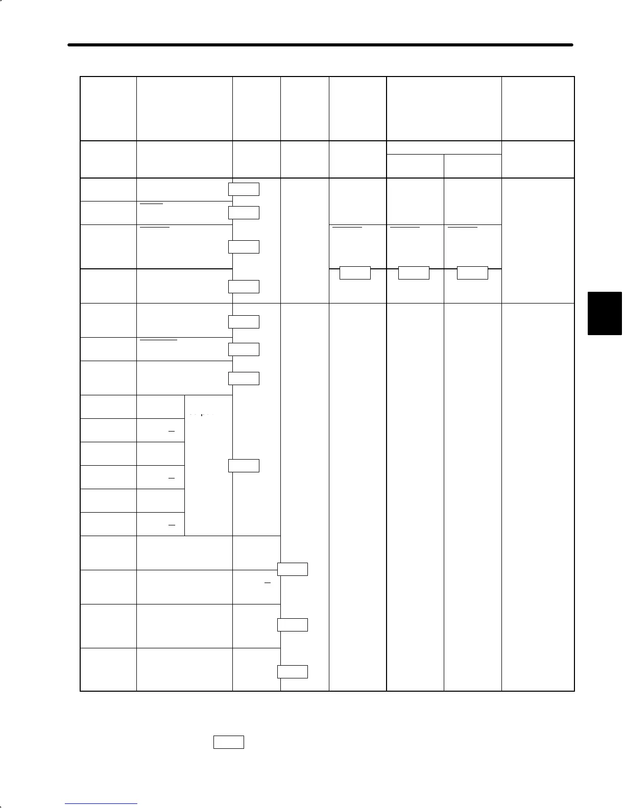
Note Information described in the “Standard Specifications” column is also applicable to blank col-
umns.
Number “x.x.x” in box represents a section number corresponding to each signal name. For
example,
3.2.1
represents Section 3.2.1.
C
1CN Terminal No.
3.2.4
3.7.2
3.2.1
3.7.1
3.2.3
3.1.2
3.1.2
3.2.3
3.8.5
3.8.5
3.8.5
3.4.3 3.2.6 3.2.6

Table of Contents

Questions and Answers:

Question and Answer IconNeed help?

Do you have a question about the YASKAWA SGDA series and is the answer not in the manual?

YASKAWA SGDA series Specifications

General IconGeneral
BrandYASKAWA
ModelSGDA series
CategoryServo Drives
LanguageEnglish

Related product manuals