4.7 Absolute Encoders
4-43
4.7.5 Absolute Data Reception Sequence
The sequence in which the SERVOPACK receives outputs from the absolute encoder and transmits them to
host controller is shown below.
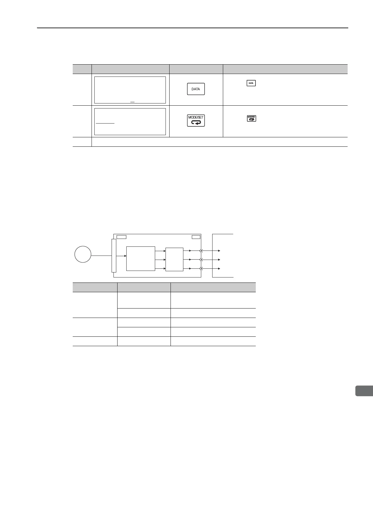
(1) Outline of Absolute Data
The serial data, pulses, etc., of the absolute encoder that are output from the SERVOPACK are output from the
PAO, PBO, and PCO signals as shown below.
Phase-C Output Specifications
The pulse width of phase C (origin pulse) changes depending on the encoder output pulse (Pn212), becoming
the same width as phase A.
The output timing is one of the following.
• Synchronized with the rising edge of phase A
• Synchronized with the falling edge of phase A
• Synchronized with the rising edge of phase B
• Synchronized with the falling edge of phase B
Note: When host controller receives the data of absolute encoder, do not perform counter reset using the output of PCO
signal.
4
Press the Key to setup the absolute encoder.
After completing the setup, "DONE" is flashed for
approximately one second and "BB" is displayed.
5
Press the Key to return to the display of the pro-
cedure 1.
6 To enable the change in the setting, turn the power OFF and ON again.
(cont’d)
Step Panel Display Keys Description
BB
Multiturn Clear
PGCL5
BB
Fn006:AlmHist Clr
Fn008:Mturn Clr
Fn009:Ref Adj
Fn00A:Vel Adj
- FUNCTION-
Signal Name Status Contents
PAO
At initialization
Rotational serial data
Initial incremental pulses
Normal Operations Incremental pulses
PBO
At initialization Initial incremental pulses
Normal Operations Incremental pulses
PCO Always Origin pulses
ENC
CN1
PAO
PBO
PCO
CN2
Serial
data
Serial data→
pulse conversion
Host
controller
SERVOPACK
Dividing
circuit
(Pn212)