3.3 I/O Signal Allocations
3-21
3.3 I/O Signal Allocations
This section describes the I/O signal allocations.
3.3.1 Input Signal Allocations
Input signals are allocated as shown in the following table.
Refer to the Interpreting the Input Signal Allocation Tables and change the allocations accordingly.
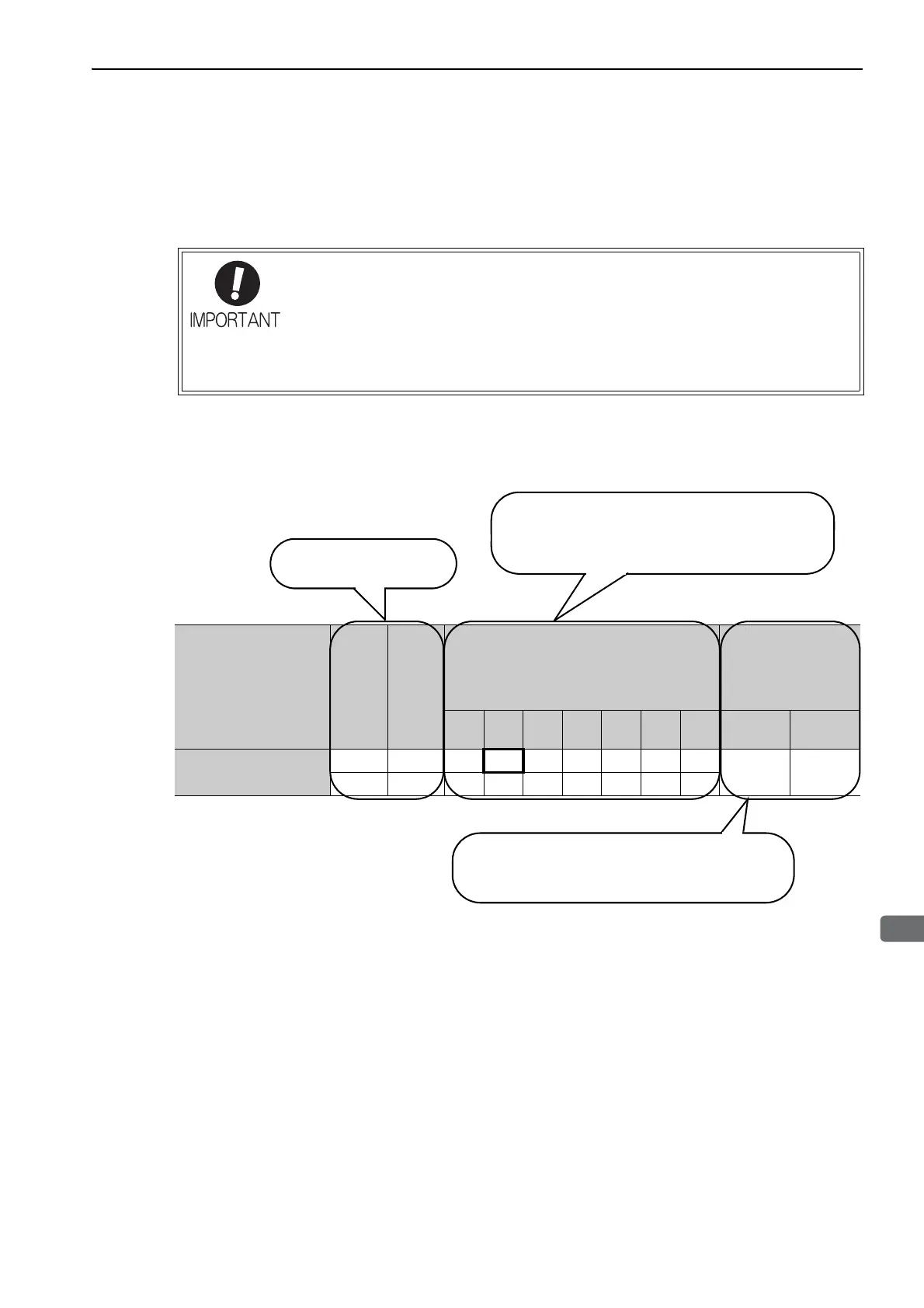
<Interpreting the Input Signal Allocation Tables>
• Inverting the polarity of the forward run prohibited and reverse run prohibited signals
from the factory setting will prevent the overtravel function from working in case of sig-
nal line disconnections or other failures.
If this setting is absolutely necessary, check the operation and confirm that there are
no safety problems.
• When two or more signals are allocated to the same input circuit, input signal level is
valid for all allocated signals, resulting in an unexpected machine operation.
Input Signal Names
and Parameters
Validity
Level
Input
Signal
CN1 Pin Numbers
Connection Not
Required
(SERVOPACK
judges the connec-
tion)
13 7 8 9 10 11 12
Always
ON
Always
OFF
Forward Run Prohibited
Pn50A.3
H P-OT0123456
78
L/P-OT9ABCDEF
Level at which input signal
allocations are valid.
The parameter set values to be used are shown.
Signals are allocated to CN1 pins according to the
selected set values.
Values in cells in bold lines are the factory settings.
If always ON (7) or always OFF (8) is set, signals
will be processed in the SERVOPACK, which will
eliminate the need for wiring changes.