8 Fully-closed Loop Control
8.1.6 Precautions When Using an External Incremental Encoder by Magnescale
8-8
8.1.6 Precautions When Using an External Incremental Encoder by Magnescale
When an external incremental encoder by Magnescale Co., Ltd. is used, the count direction of the encoder
determines if an encoder dividing phase-C pulse (CN1-21, CN1-22) is output and counted.
Note: The count direction (counting up or down) of the encoder determines if a phase-C pulse is output. The output of the
pulse does not depend on the settings of these parameters: Pn000.0 (motor rotational direction) and Pn002.3 (exter-
nal encoder usage method).
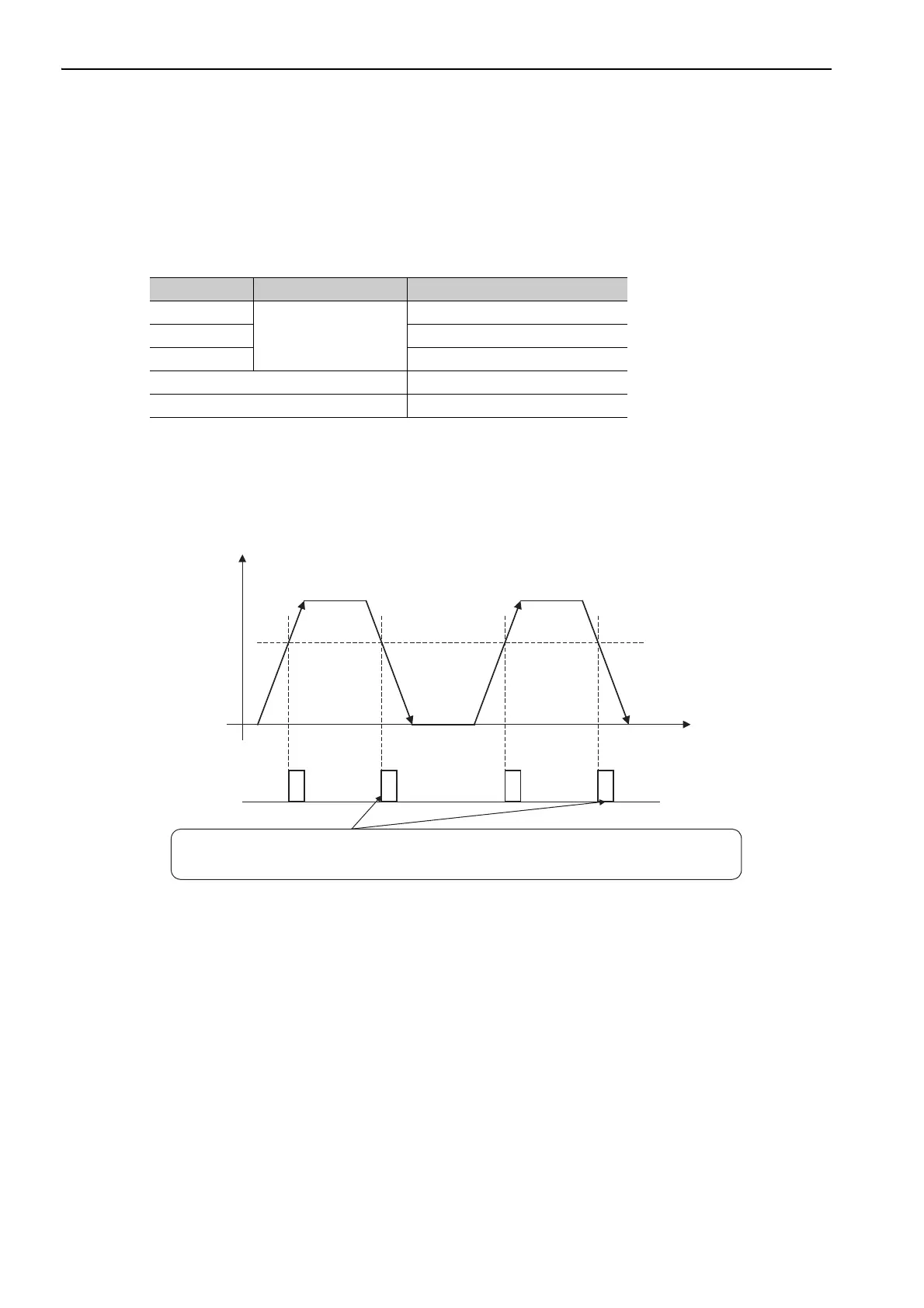
Passing First Zero Point in Forward Direction and Returning after Power ON
When the zero point detection position is first passed in the forward direction after turning the power supply
OFF and ON again, the encoder dividing phase-C pulse (CN1-21, CN1-22) is output. Then the encoder divid-
ing phase-C pulse is output when the zero point detection position is passed in either the forward or reverse
direction.
Model Interpolator Scale pitch (μm)
SL710
PL101-RY
800
SL720 800
SL730 800
SR75 80
SR85 80
Scale count-up
direction
Zero point
detection position
Power ON
Time
Phase-C pulse
output
The phase-C pulse is also output when the detection head of the encoder passes
this point in reverse, because the SERVOPACK has recorded the position
where the phase-C pulse was originally output when first passing the position in the forward direction.