3.4 Examples of Connection to Host Controller
3-25
(2) Safety Input Circuit
As for wiring input signals for safety function, input signals make common 0 V. It is necessary to make an
input signal redundant.
3.4.2 Sequence Output Circuit
Three types of SERVOPACK output circuit are available.
(1) Photocoupler Output Circuit
Photocoupler output circuits are used for servo alarm (ALM), servo ready (/S-RDY), and other sequence out-
put signal circuits. Connect a photocoupler output circuit through a relay or line receiver circuit.
Note: The maximum allowable voltage and current range of the photocoupler output circuit are as follows:
• Maximum allowable voltage: 30 VDC
• Current range: 5 to 50 mA DC
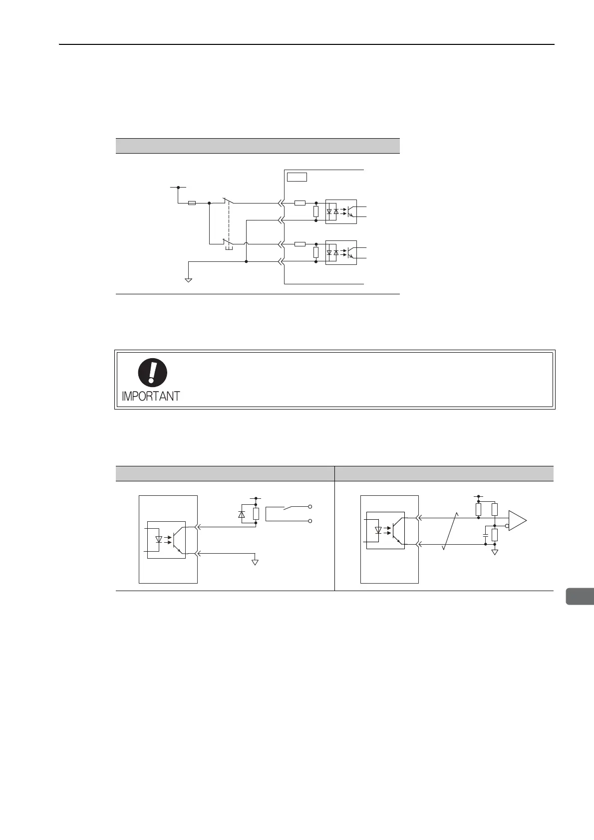
Input Signal Connection Example
24-V power supply
Switch
Fuse
/HWBB1+
4
3
/HWBB1-
/HWBB2+
/HWBB2-
3.3 kΩ
CN8
3.3 kΩ
SERVOPACK
6
5
3.3 kΩ
3.3 kΩ
Incorrect wiring or incorrect voltage application to the output circuit may cause short-cir-
cuit.
If a short-circuit occurs as a result of any of these causes, the holding brake will not
work. This could damage the machine or cause an accident resulting in death or injury.
Relay Circuit Example Line Receiver Circuit Example
0V
Relay
5 to 24 VDC
SERVOPACK