3 Wiring and Connection
3.2.3 Example of I/O Signal Connections
3-20
3.2.3 Example of I/O Signal Connections
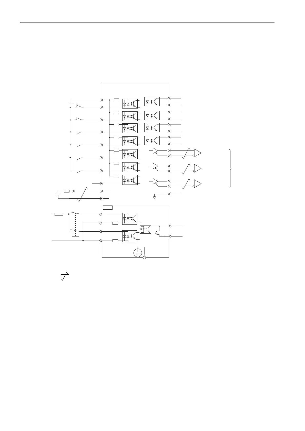
The following diagram shows a typical connection example.
∗1. represents twisted-pair wires.
∗2. Connect when using an absolute encoder. When the encoder cable with the battery case is connected, do not connect
a backup battery.
∗3. The 24-VDC power supply is not included. Use a 24-VDC power supply with double insulation or reinforced insula-
tion.
∗4. When using a safety function device, refer to 4.9 Safety Function. When not using a safety function device, leave the
safety function’s jumper connector that is included with the SERVOPACK inserted in CN8.
∗5. Always use line receivers to receive the output signals.
Note: The functions allocated to the input signals /DEC, P-OT, N-OT, /EXT1, /EXT2, and /EXT3 and the output signals
/SO1, /SO2, and /SO3 can be changed by using the parameters. For details, refer to 3.3.1 Input Signal Allocations
and 3.3.2 Output Signal Allocations.
SO1+ / BK+
SO1- / BK-
/SO2+
/SO2-
/SO3+
ALM+
ALM-
1
2
23
24
3
4
+24VIN
+24 V
3.3 kΩ
6
8
10
9
11
12
/SI0
P-OT
N-OT
/DEC
/EXT1
/EXT2
/EXT3
13
7
/SO3-
SERVOPACK
25
26
16
SG
*
1
*
2
*
3
PBO
PCO
/PBO
PAO
/PAO
/PCO
21
17
18
19
20
22
EDM1+
EDM1-
FG
/HWBB1+
/HWBB1-
/HWBB2+
/HWBB2-
24 V
0 V
Safety function device
*
4
CN8
6
3
4
5
8
7
Encoder output
pulse phase A
Encoder output
pulse phase B
Encoder output
pulse phase C
Applicable line receiver:
SN75ALS175 or
MC3486 manufactured
by Texas Instruments or
the equivalent
Photocoupler output
Max. allowable voltage: 30 VDC
Max. allowable current: 50 mA DC
Connect shield to
connector shell.
Connector
shell
SERVOPACK
Switch
Fuse
General-
purpose
Servo alarm output
(OFF for an alarm)
Brake
(Brake released when ON)
Reverse run prohibited
(Prohibited when OFF)
Forward run prohibited
(Prohibited when OFF)
External latch signal 1
(Latched when ON)
External latch signal 2
(Latched when ON)
External latch signal 3
(Latched when ON)
Homing deceleration
switch
(Decelerated when ON)
Control power supply
for sequence signal
Backup
battery
(2.8 to 4.5 V)
*
5
*
5
*
5
14
15
BAT (+)
BAT (-)
+
-