8.1 System Configuration and Connection Example for SERVOPACK with Fully-closed Loop Control
8-3
8
Fully-closed Loop Control
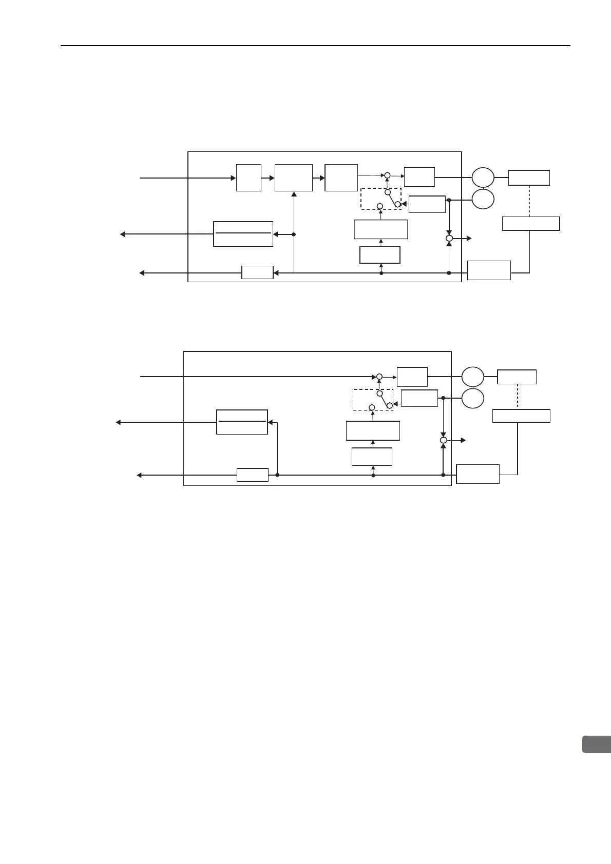
8.1.2 Internal Block Diagram of Fully-closed Loop Control
Internal block diagram of fully-closed loop control is shown below.
With Position Control
∗ The connected devices depend on the type of external encoder (linear scale).
Note: Either an incremental or an absolute encoder can be used. When the absolute encoder is used, set 1 to Pn002.2 (use
the absolute encoder as an incremental encoder).
With Speed Control
∗ The connected devices depend on the type of external encoder (linear scale).
Elec-
tronic
gear
MECHATROLINK
move command
Encoder
output
pulse
Error
counter
Speed
loop
Alarm
detection
Divider
Machine
SERVOPACK
Position
control
loop
Serial
conversion
Motor
A.d10
Encoder
External encoderࠉ
Speed
conversion
Speed
feedback
Electronic gear
1
MECHATROLINK
Monitor data
㸫
Pn22A
㸩
Speed
conversion
Unit conversion
Pn20A
*
SERVOPACK
Encoder
output
pulse
Divider
Speed
loop
Machine
Motor
Encoder
External encoderࠉ
Speed
conversion
Speed feedback
Serial
conversion
MECHATROLINK
move command
Electronic gear
1
MECHATROLINK
monitor data
㸫
Pn22A
㸩
Speed
conversion
Unit conversion
Pn20A
Alarm
detection
A.d10
*