4.4 Trial Operation
4-27
4.4.4 Encoder Output Pulses
The encoder pulse output is a signal that is output from the encoder and processed inside the SERVOPACK. It
is then output externally in the form of two phase pulse signal (phases A and B) with a 90° phase differential.
It is used as the position feedback to the host controller.
Signals and output phase form are as shown below.
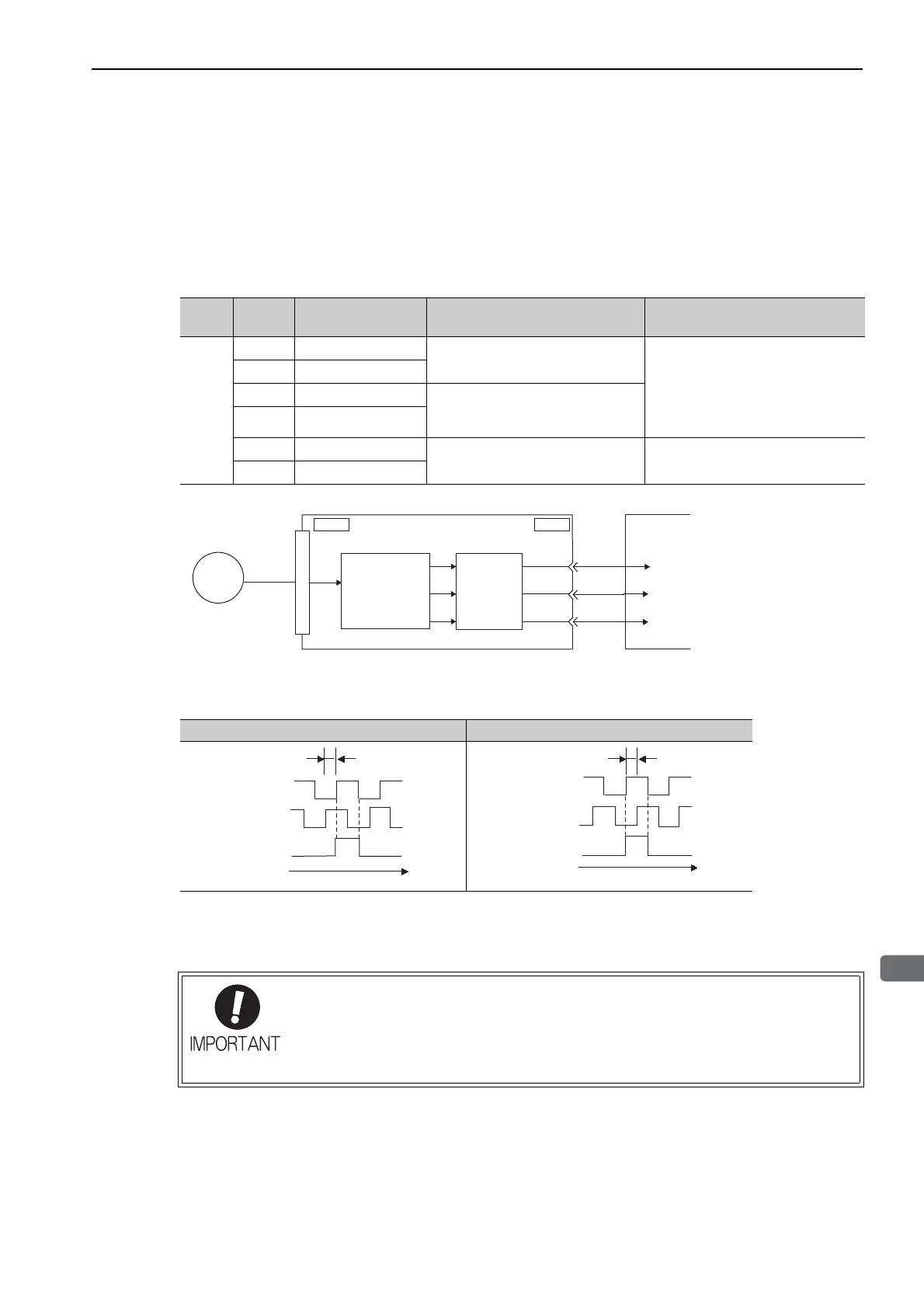
(1) Signals
(2) Output Phase Form
Note: The pulse width for phase C (origin pulse) changes according to the setting of the encoder output pulses (Pn212) and
becomes the same as that for phase A.
Even in reverse rotation mode (Pn000.0 = 1), the output phase form is the same as that for the standard setting
(Pn000.0 = 0) above.
Type
Signal
Name
Connector
Pin Number
Name Remarks
Output
PAO CN 1-1 7
Encoder output pulse: phase A
These encoder pulse output pins out-
put the number of pulses per motor
revolution that is set in Pn212. Phase
A and phase B are different from
each other in phase by an electric
angle of 90°.
/PAO CN1-18
PBO CN1-19
Encoder output pulse: phase B
/PBO CN1-20
PCO CN1-21
Encoder output pulse: phase C
One pulse is output per motor rota-
tion.
/PCO CN1-22
CN1CN2
PAO
PBO
PCO
ENC
SERVOPACK Host controller
Serial
data
Converts serial
data to pulse.
Dividing
circuit
(Pn212)
Forward rotation (phase B leads by 90°) Reverse rotation (phase A leads by 90°)
If using the SERVOPACK’s phase-C pulse output for a zero point return, rotate the ser-
vomotor two or more times before starting a zero point return. If the servomotor cannot
be rotated two or more times, perform a zero point return at a motor speed of 600 min
-1
or below. If the motor speed is faster than 600 min
-1
, the phase-C pulse may not be out-
put correctly.
Phase A
Phase B
Phase C
90
°
t
Phase A
Phase B
Phase C
90°
t