3 Wiring and Connection
3.4.2 Sequence Output Circuit
3-26
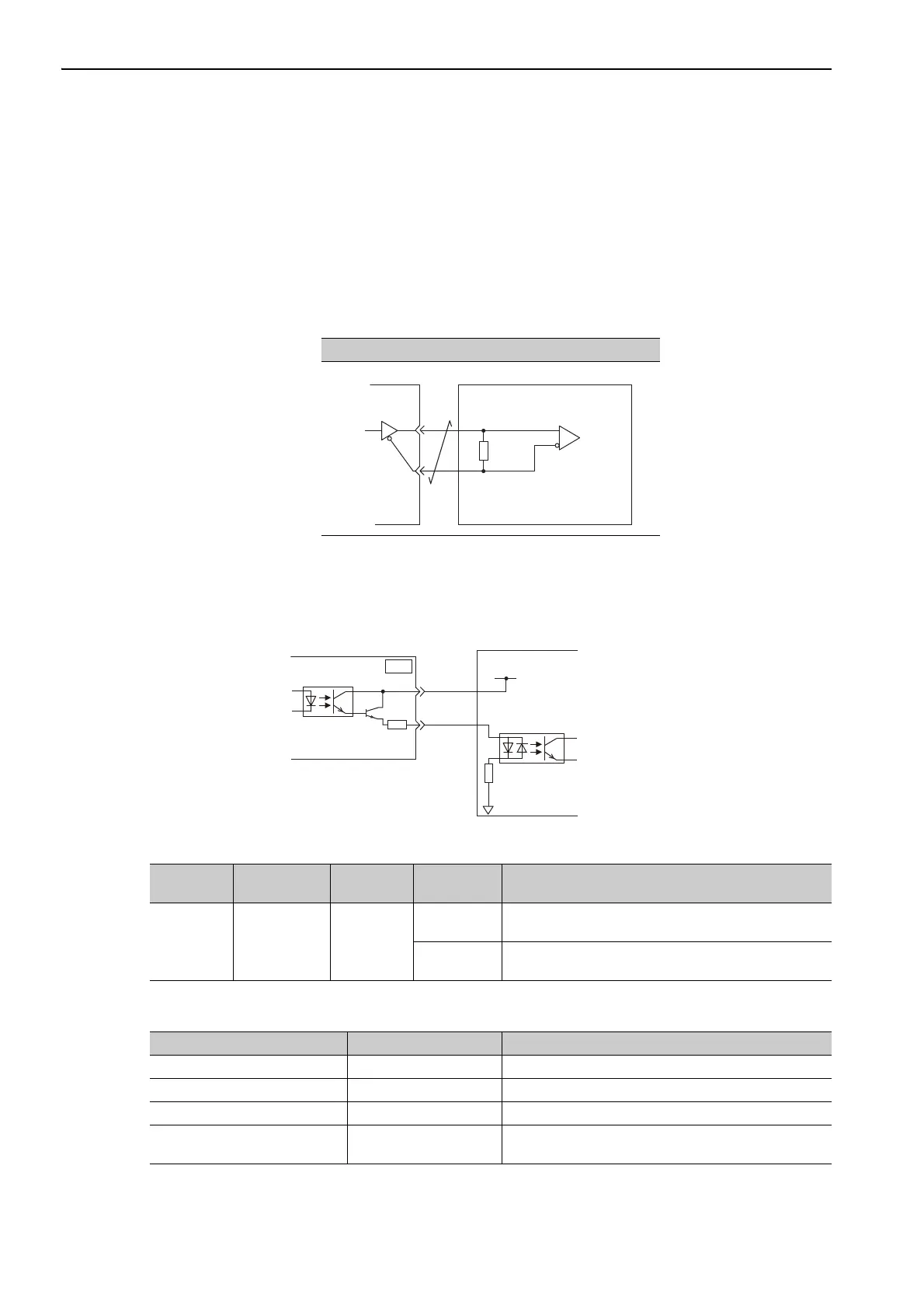
(2) Line Driver Output Circuit
CN1 connector terminals, 17-18 (phase-A signal), 19-20 (phase-B signal), and 21-22 (phase-C signal) are
explained below.
These terminals output the following signals via the line-driver output circuits.
• Output signals for which encoder serial data is converted as two phases pulses (PAO, /PAO, PBO, /PBO)
• Origin pulse signals (PCO, /PCO)
Connect the line-driver output circuit through a line receiver circuit at the host controller.
(3) Safety Output Circuit
The external device monitor (EDM1) for safety output signals is explained below.
A configuration example for the EDM1 output signal is shown in the following diagram.
Specifications
Electrical characteristics of EDM1 signal are as follows.
Line Receiver Circuit Example
SERVOPACK Host Controller
Applicable line receiver:
SN75ALS175 or the
equivalent
220 to
470 Ω
EDM1+
EDM1-
0 V
8
7
CN8
24 V Power Supply
SERVOPACK
Host controller
Type Signal Name Pin No.
Output
Status
Meaning
Output EDM1
CN8-8
CN8-7
ON
Both the /HWBB1 and /HWBB2 signals are working nor-
mally.
OFF
The /HWBB1 signal, the /HWBB2 signal, or both are not
working normally.
Items Characteristic Remarks
Maximum Allowable Voltage 30 VDC −
Maximum Allowable Current 50 mADC −
Maximum Voltage Drop at ON 1.0 V Voltage between EDM1+ to EDM1- at current is 50 mA.
Maximum Delay Time 20 ms
Time from the change in /HWBB1 or /HWBB2 until the
change in EDM1.