4.3 Basic Functions Settings
4-11
∗2. After the SV_ON command is sent, wait at least for the brake release time plus 50 ms, and then output the reference
from the host controller to the SERVOPACK.
∗3. Set the brake operation and servo OFF timing with Pn506, Pn507, and Pn508.
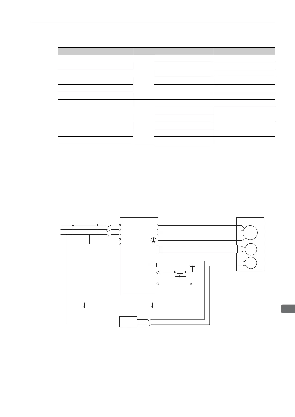
(1) Wiring Example
Use the brake signal (/BK) and the brake power supply to form a brake ON/OFF circuit. The following dia-
gram shows a standard wiring example.
The timing can be easily set using the brake signal (/BK).
Model Voltage Brake Release Time (ms) Brake Applied Time (ms)
SGMJV-A5 to 04
24 VDC
60 100
SGMJV-08 80 100
SGMAV-A5 to 04 60 100
SGMAV-06 to 10 80 100
SGMPS-01, -08 20 100
SGMPS-02, -04, -15 40 100
SGMGV-03 to 20
24 VDC,
90 VDC
100 80
SGMGV-30, -44 170 100 (24 VDC), 80 (90 VDC)
SGMGV-55, -75, -1A 170 80
SGMGV-1E 250 80
SGMSV-10 to 25 170 80
SGMSV-30 to 50 100 80
M
BK
ENC
U
V
W
CN2
AC DC
BK-RY
BK-RY
+24 V
L1
L2
L3
L1C
L2C
(/BK+)
(/BK-)
CN1
1D
0 V
BK-R Y
: Brake control relay
A 24 VDC power supply is not included.
Brake power supply for 90 V Input voltage 200-V models: LPSE-2H01-E
Input voltage 100-V models: LPDE-1H01-E
Servomotor
with holding
brake
SERVOPACK
Power supply
Red
Black
Blue or
yellow
White
Brake power
supply
DC side
AC side