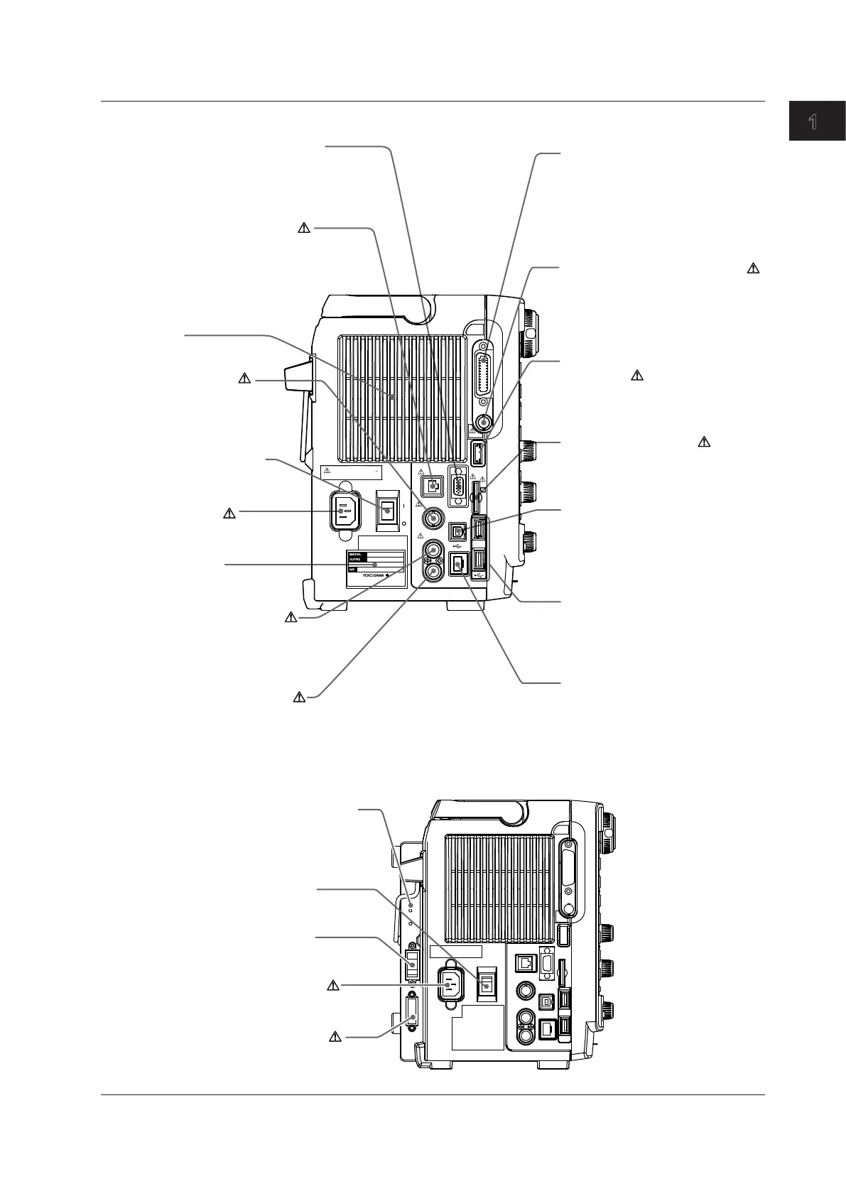
Vent
GP-IB connector (optional)
Use to communicate with the DL850
/DL850V through the GP-IB interface.
For information about the DL’s
communication features, see the
communications interface user’s
manual.
Video signal output terminal
You can output the displayed image in an
XGA RGB signal.
Explanation about how to use → Section 5.4
Main power switch
Turning the power on and off
→ Section 3.4
Name plate
Power inlet
Power connection
→ Section 3.4
External HDD connector
(optional)
Use to connect an external hard disk.
Explanation about how to use
→ User’s manual
USB port for PCs
Use to connect the DL850/DL850V
to a PC that has a USB port.
Explanation about how to use
→ Communication interface user’s
manual
USB ports for peripherals
Use to connect a USB keyboard,
mouse, or storage device.
Explanation about how to use
→ Section 4.3 and User’s manual
Trigger output terminal
Use to transmit trigger signals.
Explanation about how to use
→ Section 5.2
Made in Japan
GP- I B
(
IEE E48 8
)
IRI G
EXT HDD
SD
VID E O OU T
(
XGA
)
EXT CLKI N
EXT I/O
TRI G GER
IN
OUT
ETH E RNET
100 0 BASE - T
POW E R
ON
OFF
100 - 120/ 2 20-2 4 0 V A C
200 VA M A X 50 / 60 H z
GO/NO-GO and external
start/stop I/O connector
Transmits GO/NO-GO determination
I/O signals.
Can also be used to start and stop
the DL850/DL850V through external control.
Explanation about how to use
→ Section 5.5
External-clock
input terminal
Use when applying an
external clock signal.
Explanation about how to use
→ Section 5.3
Trigger input terminal
Use when applying an external
trigger signal.
Explanation about how to use
→ Section 5.1
Ethernet port (100BASE-TX)
Use to connect the DL850/DL850V
to a LAN.
Explanation about how to use
→ Feature’s guide and communication
interface user’s manual
IRIG input terminal (optional)
Use when applying an external
synchronization signal (IRIG signal).
Explanation about how to use
→ Section 5.6
SD memory card slot
Use to connect an SD memory card.
Explanation about how to use
→ User’s manual

 Loading...


