2-9
IM MV1000-01E
Installation and Wiring
1
2
3
4
5
6
7
8
9
10
11
12
13
App
Index
Wiring Procedure
As shown in the figure below, the optional terminal block is located on the rear panel. The
MV is only equipped with an optional terminal block when an option that requires input/
output, such as the alarm output relay (/A options), FAIL/status output relay (/F1 option),
and remote control function (/R1 option), is installed . There is a terminal cover screwed
onto the optional terminal block. It has a label indicating the terminal arrangement on it.
1.
Turn OFF the MV and remove the terminal cover.
2.
Connect the signal wires to the terminals.
The recommended torque for tightening the
screws is 0.9 to 1.0
N•m.
3.
Replace the terminal cover and fasten it with screws. The appropriate tightening
torque for the screws is 0.6 N•m.
Optional Terminal Arrangement
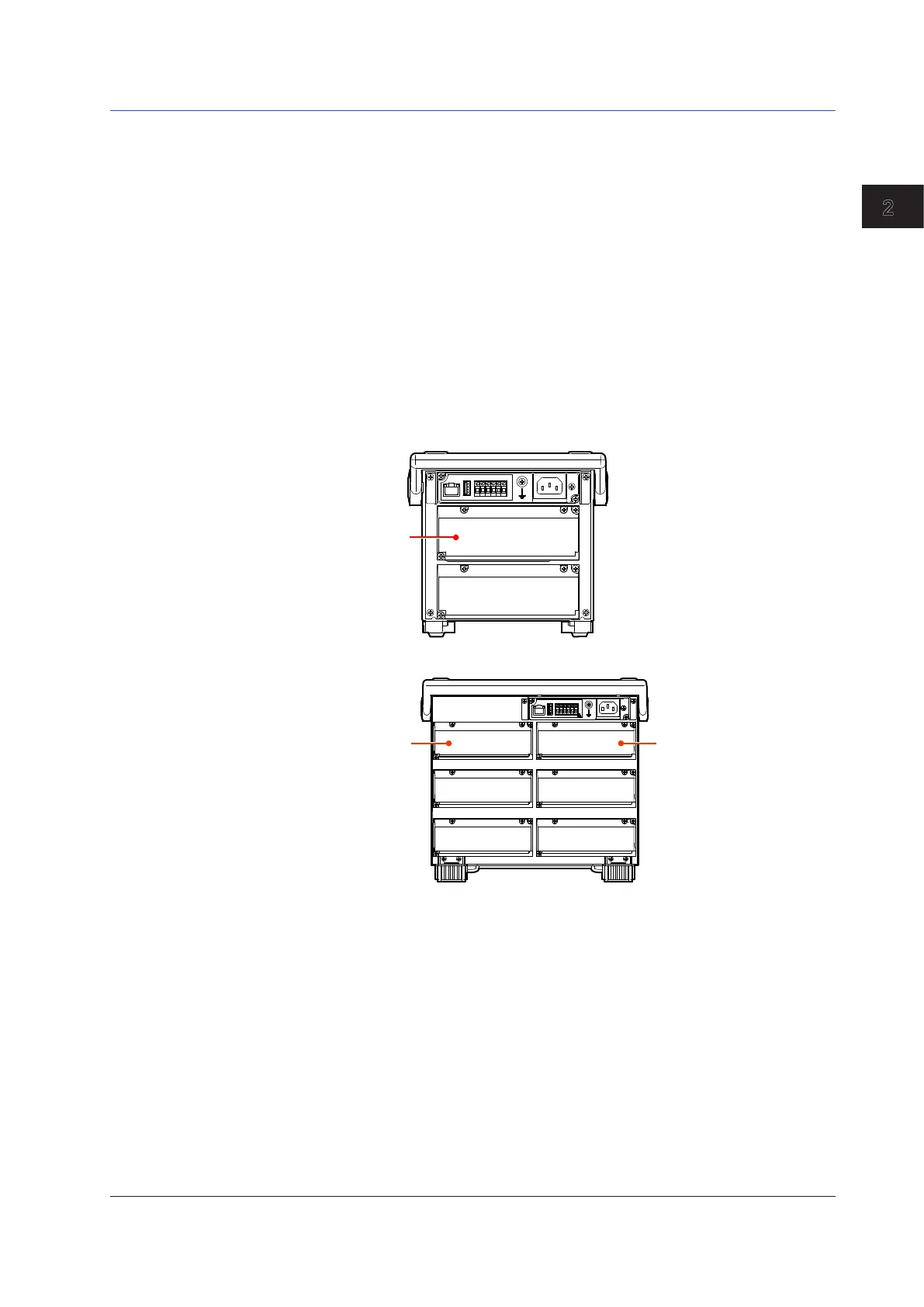
Location of the Optional Terminal Blocks
• MV1000
Optional terminal
block 1
• MV2000
Optional terminal
block 1
Optional terminal
block 2
2.3 Optional Terminal Wiring

 Loading...