2-13
IM MV1000-01E
Installation and Wiring
1
2
3
4
5
6
7
8
9
10
11
12
13
App
Index
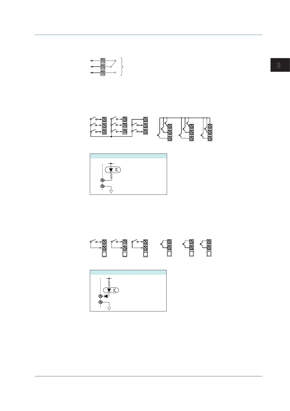
Alarm Output Terminal, FAIL Output Terminal, and Status Output Terminal (/A1,
/A2, /A3, /A4, and /F1)
C
NC
NO
Output format: Relay contact
Contact rating: 250 VAC (50/60 Hz)/3 A, 250 VDC/0.1 A (for resistor load)
Withstand voltage: 1600 VAC at 50/60 Hz for one minute
(between output terminals and the ground terminal)
Remote Control Input Terminal (/R1)
C
C
1
1~ 8
2
3
4
5
6
7
8
• Transistor input (open collector)
Internal circuit
• Relay contact input
(voltage-free contact)
C
1
2
3
4
5
6
7
8
Withstand voltage: 1000 VDC for one minute between
input terminals and the ground terminal
Input format:
Photocoupler isolation
Shared common (C)
Allowable input voltage:
5 VDC
5 V
Contact closed at 200 Ω
Contact open at 100 kΩ or greater
ON voltage: 0.5 V or less (30 mADC)
Leakage current when turned OFF:
0.25 mA or less
Pulse Input Terminal (/PM1)
H
L
H
L
H
L
H
L
H
L
H
L
H
8 7 6
678
L
Withstand voltage: 1000 VDC for one minute between
input terminals and the ground terminal
Input format:
Photocoupler isolation
Shared common (L)
Allowable input voltage:
5 V
Internal circuit
•Transistor input (open collector)
• Relay contact input
(voltage-free contact)
Contact closed at 200 Ω or less
Contact open at 100 kΩ or greater
ON voltage: 0.5 V or less (30 mADC)
Leakage current when turned OFF:
0.25 mA or less
30 VDC
2.3 Optional Terminal Wiring

 Loading...