3-39
IM 760301-01E
3
Before Starting Measurements
3.17 Displaying the Setup Parameter List
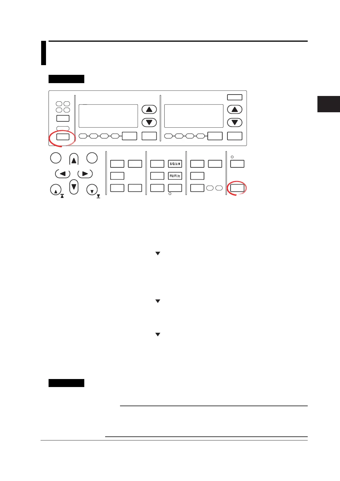
Procedure
START STOP
REMOTE
CAL
SENSOR RATIO
MEASURING
RMS MEAN DC RMEAN
CURRENT RANGEVOLTAGE RANGE
MEASURING
RMS MEAN DC RMEAN
ALL
INPUT INFO.
LOWER ITEM LOWER FORM ALLUSER SET
DISPLAY
ITEM & ELEMENT
2
34
COMPEN
ELEMENT
ELEMENT
1
WIRING
MODE AUTO MODE
AUTO
EXT SENSOR
NUMERIC
WAVE
OTHERS
ITEM
FORM
U / I / P
WP/q/
TIME
USER
ELEMENT
UPDATE
RATE
HOLD
SINGLE
INTEG
LOCAL
SHIFT
RESET SET
PAGE PAGE
Cursor keys
To exit the menu during
operation, press ESC
located above the soft
keys.
In the procedural
explanation below, the
phrase “press the cursor
keys” may be used. This
phrase refers to the
procedures for selecting
items and entering values
and character strings. For
details on the procedures,
see section 3.14.
• Displaying the Relation Table of Elements and Measurement Ranges
1. Press SHIFT+WIRING(INPUT INFO.). The relation table of measurement
ranges, input filters, transformation ratios, scaling factors, and other parameters
are displayed for each element.
• Displaying the Relation Table of Rotating Speeds and the Input Ranges of
Torque*
1
2. Press PAGE to display the list of motor settings. A relation table of the
rotating speed and the input range, filter, scaling factor, unit, and
synchronization source of torque, number of poles, frequency measurement
source, and other parameters is displayed.
*1 Displayed only on models with the motor evaluation function (motor version).
• Displaying the Relation Table of Trend Targets and Measurement Functions
2. Press PAGE
to display the list of trend settings. The relation table of trend
targets and measurement functions is displayed.
• Displaying the Relation Table of D/A Output Channels and Measurement
Functions*
2
2. Press PAGE to display the list of D/A output settings. The relation table of D/
A output channels and measurement functions is displayed.
*2 Displayed only on models with the D/A output (option).
• Closing the List of Setup Parameters
3. Press SHIFT+WIRING (INPUT INFO.). The list of setup parameters closes.
Explanation
The setup parameter list is shown as in the example on the next page.
Note
The relation table of elements and measurement ranges and the relation table of the
measurement ranges of the motor evaluation function show the settings that existed when the
measurement was carried out. If you change the parameters such as the measurement range
while the hold function is ON, the change is not reflected in the relation table.

 Loading...


