App-1
IM 760301-01E
App
Appendix
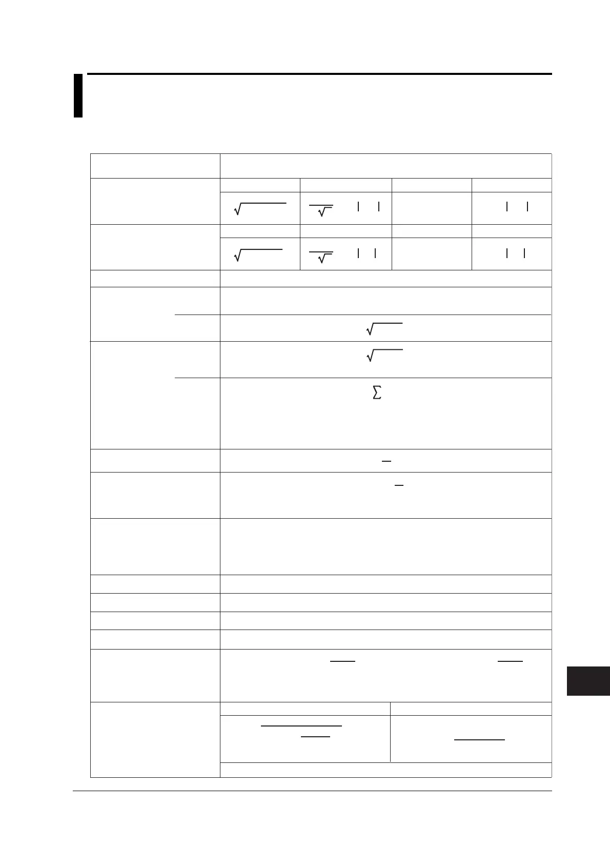
Appendix 1 Symbols and Determination of
Measurement Functions
Measurement Functions during Normal Measurement
Upk
Urms
Ipk
Irms
P
S
cos
–1
( )
P
S
Corrected Power Pc [W]
P1 + P2
(
)
2
Urms
Umn
P
Urms Umn
Udc
Urmn
True rms value
Urms
Rectified mean value calibrated
to the rms value
Umn
Simple average
Udc
Rectified mean value
Urmn
AVG[u(n)
2
]
AVG[i(n)
2
]
Irms Imn
Idc
Irmn
s is –1 or 1 for lead phase or lag phase, respectively.
Current crest factor CfI =Voltage crest factor CfU =
Voltage crest factor CfU
Current crest factor CfI
Maximum voltage U+pk [V]
Minimum voltage U-pk [V]
Maximum current I+pk [A]
Minimum current I-pk [A]
The maximum u(n) for every data update interval
The minimum u(n) for every data update interval
The maximum i(n) for every data update interval
The minimum i(n) for every data update interval
Upk = |U+pk| or |U-pk|, whichever is greater
Displays “--------” when the voltage mode
is not RMS
Ipk = |I+pk| or |I-pk|, whichever is greater
Displays “--------” when the current mode
is not RMS
Active power P [W]
Reactive power
Q [var]
TYPE1,
TYPE2
TYPE3
Apparent power S [VA]
Power factor λ
Phase difference φ [°]
Measurement Functions during
Normal Measurement
Voltage
U [V]
True rms value
Irms
Rectified mean value calibrated
to the rms value
Imn
Simple average
Idc
Rectified mean value
Irmn
Current
I [A]
The phase angle can be switched between lead (D)/lag (G) display
and 360°display.See section 5.10.
Method of Determination, Equation
For details on the symbols in the equation, see the Note on page App-3.
Voltage frequency
fU (FreqU) [Hz]
Current frequency
fI (FreqI) [Hz]
Coefficients defined in the applicable standard
Displays “--------” when the voltage mode is not RMS or MEAN.
IEC76-1(1976), IEEE C57.12.90-1993
P
(
1 +
)
Umn – Urms
Umn
IEC76-1(1993)
(Continues to the next pa
e)
(Table 1/3)
π
2
2
AVG[ i(n) ]
π
2
2
AVG[ u(n) ]AVG[ u(n) ]
AVG[ i(n) ]
AVG[u(n)]
AVG[i(n)]
The voltage frequency (fU) and current frequency (fI) are measured using zero crossing
detection. Two frequencies from the fU and fI of all installed elements (including the
PLL source frequency) can be measured simultaneously.
On the model with the frequency measurement add-on option, the fU and fI of all
elements can be measured simultaneously.
Q(k) = Ur(k) • Ij(k) – Uj(k) • Ir(k)
Ur(k) and Ir(k) are the real part components of U(k) and I(k)
Uj(k) and Ij(k) are the imaginary part components of U(k) and I(k)
Valid only when harmonics are being measured correctly.
Q(k)
k = min
max
AVG[u(n) • i(n) ]
U
• I
TYPE1,
TYPE2
TYPE3
P
2
+ Q
2
S
2
– P
2
s •
Appendix

 Loading...


