2-1
IM 760301-01E
2
Faunctional Description
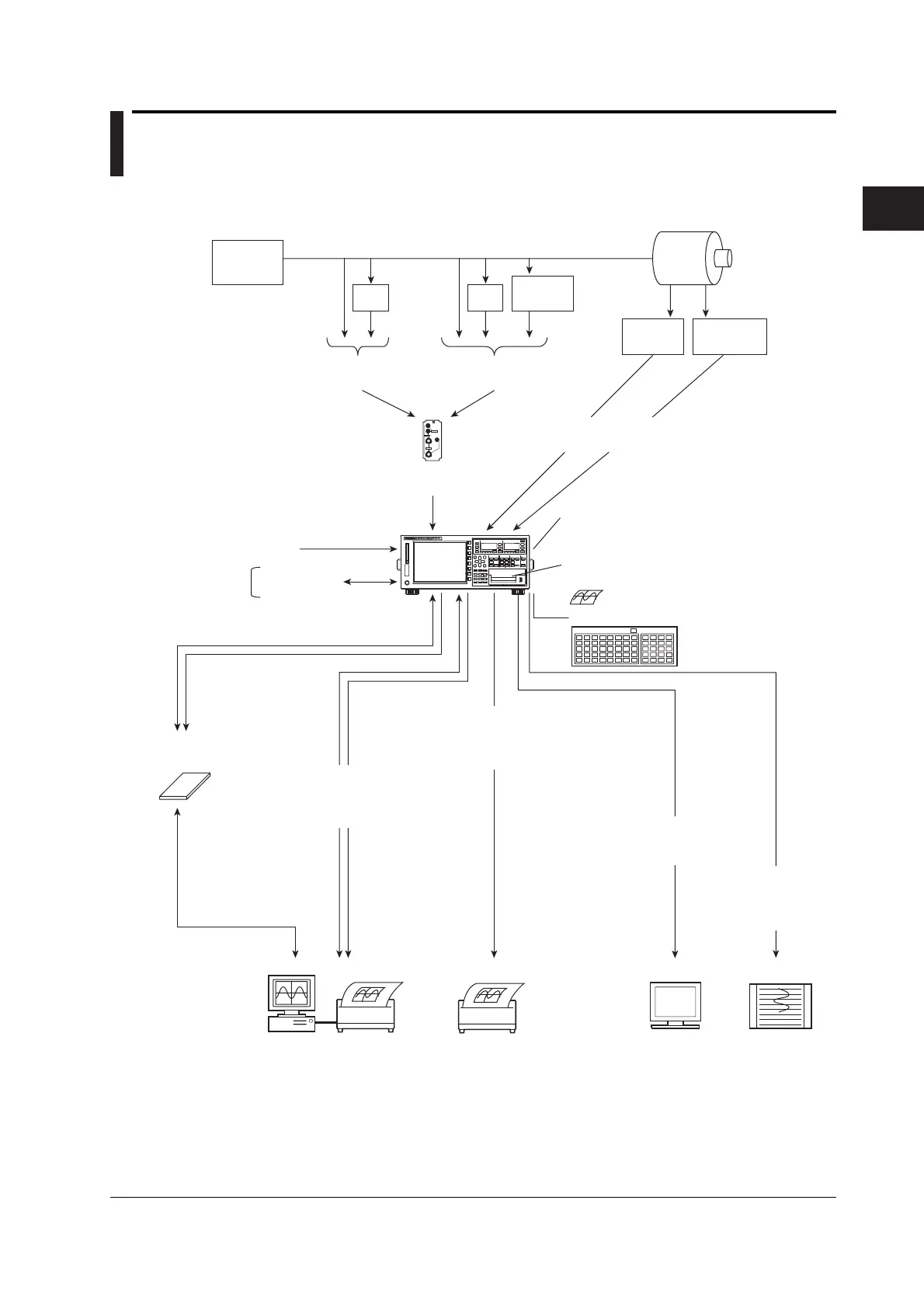
2.1 System Configuration and Block Diagram
System Configuration
ELEMENT
VOLTAGE
±
±
CURRENT
EXT
Power
supply
Load
Motor
VT
CT
Voltage
(Input either one)
Current
(Input either one)
Current
sensor
Revolution
sensor
Torque
meter
Input element
Motor evaluation
(Motor version)
External clock input
Master/slave
sync signal
Built-in printer (option)
Print screen image data/numeric data list
Internal memory
Store numeric data and waveform display data
Recall numeric data and waveform display data
PC card/
USB memory (option)
CRT
Recorder
Numeric data
Waveform display data
Screen image data
Store data
Setup parameters
Numeric data
Waveform display data
Screen image data
Setup parameters
PC
Printer
D/A output (option)
Output the measured
values as analog
voltage
Network printer
Ethernet interface
(option)
Screen image/
numeric data list
Measurement
start/stop
GP-IB interface/
RS-232 interface (option)/
Ethernet interface (option)/
USB interface (option)
RGB video signal
(VGA) output (option)
Image signal
USB keyboard (option)
Chapter 2 Functional Description
 Loading...


