1-1
IM 760301-01E
1
Names and Functions of Parts
1.1 Front Panel, Rear Panel, and Top Panel
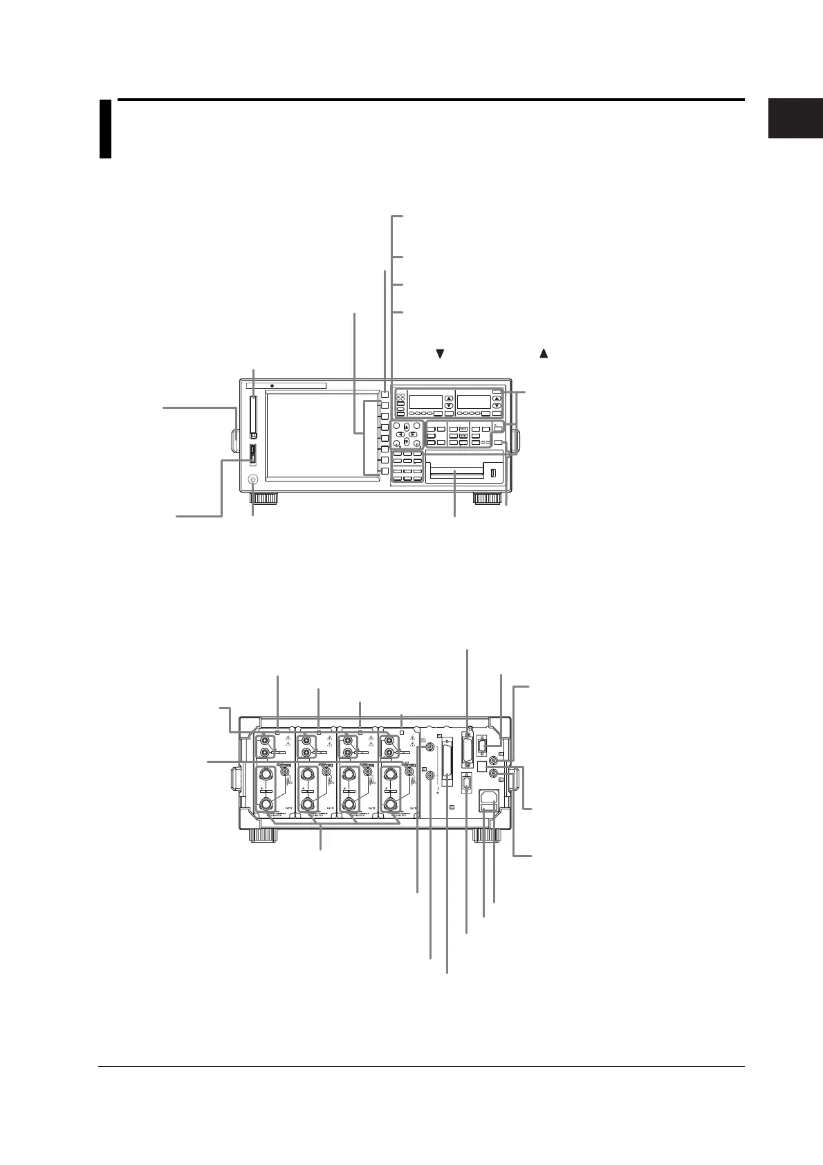
Front Panel
START STOP
REMOTE
CAL
SENSOR RATIO
MEASURING
RMS MEAN DC RMEAN
CURRENT RANGEVOLTAG E RAN G E
MEASURING
RMS MEAN DC RMEAN
ALL
INPUT INFO.
MOTOR
SET
CURSOR NULL
MENU STORE SET
MENU
LOWER ITEM LOWER FORM ALLUSER SET
DISPLAY
ITEM & ELEMENT
2
34
COMPEN
ESC
ELEMENT
ELEMENT
1
WIRING
MODE AUTO MODE AUTO
EXT SENSOR
RESET SET
PAGE PAGE
SCALING
HRM SET
MEASURE
SYNC SOURCE
AVG
LINE FILTER
FREQ
FILTER
FILE
PRINT
MISC
STORE
IMAGE SAVE
HELP
NUMERIC
WAVE
OTHERS
ITEM
FORM
U / I / P
WP/q/
TIME
USER
ELEMENT
UPDATE
RATE
HOLD
SINGLE
INTEG
LOCAL
SHIFT
YOKOGAWA
WT3000
PRECISION POWER ANALYZER
MOTOR VERSION
LCD
ESC key
Clear a setup menu or
dialog box.
Soft keys
Selects items on the setup menu
that appears on the screen.
PC card slot
Used when saving data to a
PC card. (See section 9.1)
Handle
Use the handles (both
sides) when moving
the instrument. (See
section 3.1)
Power switch.
(See section 3.4)
Cursor keys
Sets values (includes the movement between digits), moves the
cursor, and selects items in setup operations.
SET key
Enters (Confirms) the item or value set using the cursor keys.
RESET key
Resets the value entered using the cursor keys to default.
PAGE key
Because all measurement items cannot fit on one screen, the
WT3000 displays the measurement items on separate pages. The
PAGE key and the PAGE key is used to switch the displayed
page. (See section 5.1)
Setup Menu Display Key and
ExecutionKey
Keys that are pressed first when entering a
setting or executing an operation. Press
the setup menu display key to open various
setup menus. Press an execution key to
execute the operation assigned to that key.
(See section 1.2)
SHIFT key
The keys enter the shifted state when you press
the SHIFT key and the SHIFT key illuminates.
In this state, the setup menu marked in purple
below the panel keys can be selected.
Built-in printer (option)
Used to print screen images.
(See the Expansion Function
User’s Manual IM760301-51E)
USB port
Connect a USB
memory or USB
keyboard.
Rear Panel
TORQUE
± 20V MAX
± 20V MAX
SPEED
42Vpk MAX
D/A OUTPUT
VIDEO-OUT
(VGA)
GP-IB
(IEEE488)
SERIAL
(RS-232)
/ USB
EXT. CLK
ETHERNET
100BASE-TX
MEAS. START
100-240V AC 50/60Hz
200VA MAX
FUSE 250V T 6.3A
ELEMENT
VOLTAGE
±
1000V
MAX
1000V
MAX
±
CURRENT
1
30A
MAX
ELEMENT
VOLTAGE
±
1000V
MAX
1000V
MAX
±
CURRENT
2
30A
MAX
ELEMENT
VOLTAGE
±
1000V
MAX
1000V
MAX
±
CURRENT
3
30A
MAX
ELEMENT
VOLTAGE
±
1000V
MAX
1000V
MAX
±
CURRENT
4
30A
MAX
Power connector (See section 3.3)
Power fuse (See section 11.5)
Input element 1 (See section 2.3)
Input element 2
Input element 3
Input element 4
Ethernet port (option)
(See the Expansion Function User’s
Manual IM760301-51E.)
External start signal output connector
Used when performing master/slave
synchronized measurement. (See
section 10.8)
External clock input connector
• Receives the synchronization source
(signal) that defines the
measurement/computation period. (See
section 4.7)
• Receives the external PLL source
(signal) for harmonic measurement.
See the Expansion Function
User’s
Manual IM760301-51E.
RS-232 connector or USB port (for the PC)
(Selectable option)
See the Communication Interface User’s Manual
IM760301-17E (CD-ROM).
GP-IB connector
(See the Communication Interface User’s Manual
IM760301-17E (CD-ROM).)
RGB video signal (VGA) output connector (option)
Outputs image signals. (See the Expansion Function
User’s Manual IM760301-51E.)
D/A output connector (option)
Outputs numeric data that has been converted to
analog DC voltage. (See the Expansion Function
User’s Manual IM760301-51E.)
Torque signal input connector (motor version)
Receives signals from torque meters when
evaluating motors. (See the Expansion Function
User’s Manual IM760301-51E.)
Revolution signal input connector (motor version)
Receives signals from revolution sensors when
evaluating motors. (See the Expansion Function
User’s Manual IM760301-51E.)
Current input terminal
Used to connect current measurement
cables. (See sections 3.8, 3.9, and 3.11)
External current
sensor input
connector
Used to connect the
external sensor cable
from the external
current sensor. (See
section 3.10)
Voltage input terminal
Used to connect voltage
measurement cables.
(See sections 3.8 to
3.11)
Chapter 1 Names and Functions of Parts
 Loading...


