2-4 IM 760301-01E
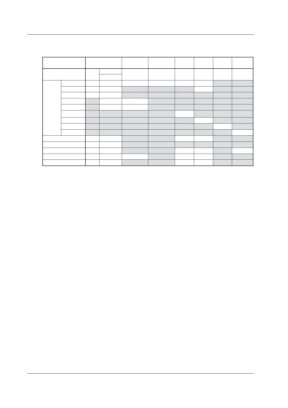
The selectable displays and main functions of each measurement mode are given below.
For a list of selectable functions, see appendix 10.
YesYesNoNoYesYes
YesYes
NoYesYesYes
YesYes
NoNoYesYes
NoNoNoNoYesYes
YesYes
NoNoYesYes
NoNoNoNoYesYes
YesYesLimit
*1
Limit
*1
YesYes
Harmonics
/G6, /G5
Option
FFT
Voltage
Fluctuation
and Flicker
Cycle by
Cycle
Waveform
Computation
IEC Harmonic
Wide Bandwidth
Harmonic
Normal MeasurementMeasurement Mode
/G6 /FL /CC/G6/G6/G6None
Data update rate
Integration
Motor
D/A
Delta computation
Display
Numeric
Waveform
Trend
Bar graph
Vector
Waveform
computation
FFT
Flicker
Cycle by Cycle
YesNoNo
*2
NoYesYes
YesNoNoNoNoNo
No
No
No
No No
No
No
No No
No No
No
No
*3
No
NoYesNoNoNoNo
NoNoNoYesYesNo
No
No
No
No
No
No
No
No
No
No
No
No
No
No
No
Yes
No
Yes
Yes
No
No
No
No
No
No
No
NoNoNo
*2
YesYesNo
*1 The rms values of the voltage or current are the total of the specified harmonic components, not the values that include all
frequency components.
*2 Can be monitored using the IEC harmonic measurement software.
*3 Fixed to 2 s.
• Differences in the Harmonic Measurement of Each Measurement Mode
In IEC harmonic measurement mode, limitation is placed on a portion of the functions
of the WT3000 as compared with the harmonic measurement in normal measurement
mode due to the measurement conditions and constraints in the standard. For details,
see the table above. During the development or inspection of a device, you can use
the harmonic measurement in normal measurement mode to measure simultaneously
the rms voltage, the rms current, the power, and harmonics in a simplified manner. To
strictly evaluate whether the device complies with the IEC standard, you can use the
IEC harmonic measurement mode. When measuring the harmonics of a high
frequency power supply whose fundamental frequency is in the order of hundred
Hertz, use the wide bandwidth harmonic measurement mode.
2.2 Measurement Modes and Measurement Functions
 Loading...


