4-23
IM 760301-01E
4
Measurement Conditions
Explanation
There are two types of input filters, line filter and frequency filter.
• Selecting the Line Filter
Because the line filter is inserted into the voltage and current measurement input
circuit, it directly affects the voltage, current, and power measurements (see the block
diagram in section 2.1). When the line filter is turned ON, the measured value does
not contain high frequency components. Therefore, measurement of voltage, current,
and power is possible by eliminating high frequency components from inverter
waveforms, strain waveforms, etc.
• The cutoff frequency can be selected from the list of choices below.
OFF, 500 Hz, 5.5 kHz, and 50 kHz
• If any of the target elements is set to a setting other than OFF, the LINE FILTER
key illuminates.
• Selecting OFF disables the line filter.
• Line Filter and Measurement Mode
• The line filter setting is common to all measurement modes except cycle-by-cycle
measurement mode. The initial setting is OFF.
• The line filter setting in cycle-by-cycle measurement mode is independent of the
setting in other measurement modes. The initial setting is 50 kHz.
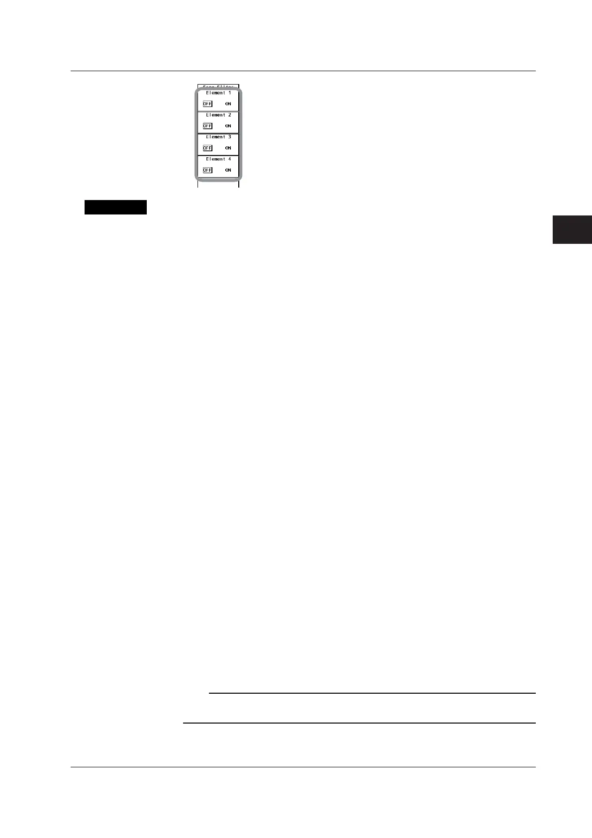
• Selecting the Frequency Filter
Because the frequency filter is inserted into the frequency measurement input circuit,
it affects frequency measurements. In addition, if the display update interval of the
WT3000 is set to 50 ms, 100 ms, 5 s, 10 s, or 20 s, it affects the detection of the
measurement period for voltage, current, and power measurements (see appendix 6
and 7). In this case, the filter also acts as a filter for detecting the zero-crossing of the
synchronization source signal (see section 2.2) more accurately. The frequency filter
is not inserted into the voltage and current measurement input circuit. Therefore, the
measured values include high frequency components even when the frequency filter
is turned ON.
• The WT3000 detects the zero crossing point with a hysteresis of approximately 5%
of the measurement range.
• If the line filter described above is ON, the line filter affects the frequency
measurement even when the frequency filter is OFF.
• It is recommended that the frequency filter be turned ON when the input signal
frequency is less than or equal to 440 Hz.
Note
For details on selecting the line filter for the motor evaluation function, see the
Expansion
Function User’s Manual IM760301-51E
.
4.8 Selecting the Input Filter
 Loading...


