5-8 IM 760301-01E
• Changing the Measurement Function
• The types of measurement functions that can be selected are the items that are
indicated in “Types of Measurement Functions during Normal Measurement” of
section 2.2, “User-Defined Function” and Corrected Power of section 2.5,
“Measurement Functions of Integration,” “Motor Evaluation Function (Motor
Version)
*
,” “Delta Computation (Option)
*
,” and “Harmonic Measurement (Option)
*
”
in section 2.6.
* For details, see the
Expansion Function User’s Manual IM760301-51E
.
• You can also select not to display the measurement functions (None).
• The number (1, 2, 3, and 4) that is attached to the measurement function symbol of
the delta computation has no relation to the element number.
• The number attached to the user-defined function F1 to F20 is a portion of the
measurement function symbol. It is not related to the element number.
• Changing the Element/Wiring Unit
• You can select the element/wiring unit from the choices below. The selectable
items vary depending on the installed elements.
Element1, Element2, Element3, Element4, ΣA, and ΣB
• If there are no elements that are assigned to the selected wiring unit, there is no
numeric data. Thus, [-------] (no data) is displayed in this case. For example, if
elements are assigned to ΣA and no elements are assigned to ΣB, then the
measurement function for ΣB shows [-------] (no data).
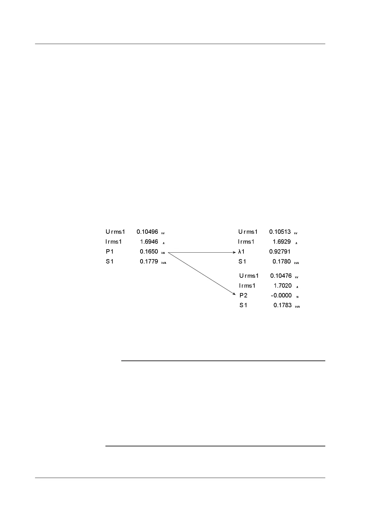
Change the measurement
function of the third item
Change the element
of the third item
• Resetting the Order of Display Items
You can reset the displayed order of numeric data to a preset order. For details on the
reset items, see appendix 2, “List of Initial Settings and Display Order of Numeric
Data.”
Note
• For the meanings of the measurement function symbols that are displayed, see section 2.2,
“Measurement Functions and Measurement Periods,” 2.5, “Computation,” 2.6, “Integration,”
appendix 1, “Symbols and Determination of Measurement Functions,” and chapter 6, “Delta
Computation” in the
Expansion Function User’s Manual IM760301-51E
.
• For the procedure of changing the displayed items of the measurement functions of harmonic
measurement, see chapter 7 in the
Expansion Function User’s Manual IM760301-51E
.
• For details on the wiring units expressed as ΣA and ΣB, see section 4.1, “Selecting the Wiring
System.”
• If you supply current exceeding approximately 2.8 Arms to the 2-A input element, the
protection circuit activates. The measured value may become 0 A, but the input peak over-
range indicator at the top section of the screen illuminates in red.
5.1 Displaying Numeric Data and Changing the Displayed Items
 Loading...


