App-27
IM 760301-01E
App
Appendix
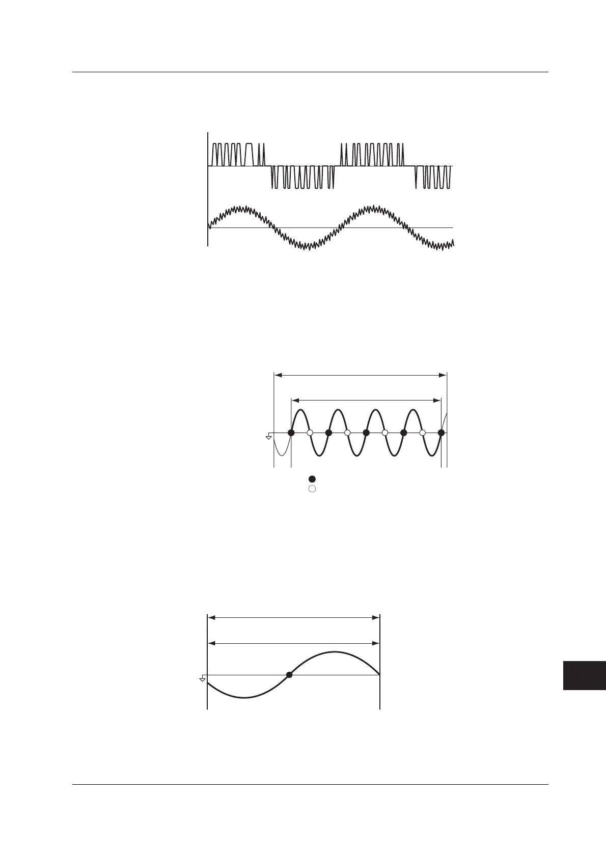
As another example, if an inverter is being measured and the distortion of current
waveforms is smaller than voltage waveforms, set the synchronization source to the
current signal.
Voltage
waveform
Current
waveform
Synchronization source
setting: Current signal
• Zero Crossing
• Rising (or falling) zero crossing refers to the time when the synchronization source
passes through level zero (center of the amplitude) on the rising (or falling) slope.
The measurement period on the WT3000 is between the first rising (or falling) zero
crossing and the last rising (or falling) zero crossing in the data update interval.
• The rising or falling zero crossing is automatically selected for the one that allows
the interval to be longer.
Data update interval
Measurement period
Synchronization
source
Zero crossing of the rise ramp
Zero crossing of the fall ramp
• When the Period of the Synchronization Source Cannot Be Detected
If there are less than two rising or falling zero crossings of the input signal set as the
synchronization source in the data update interval, the period cannot be detected. In
addition, the frequency cannot be detected if the AC amplitude is small. (For details
on the detection level for frequency measurement circuit, see section 12.5.) If this
happens, the entire data update interval becomes the measurement period, and the
sampled data of the entire period are averaged.
Data update interval
Measurement period
The measured values of voltage and current may be unstable due to causes
described above. In such case, lower the data update rate so that more periods of the
input signal fit within the data update interval.
Appendix 6 Setting the Measurement Period
 Loading...


