3-3
IM 760301-01E
3
Before Starting Measurements
Storage Location
When storing the instrument, avoid the following places:
• Where the relative humidity is 80% • Where the level of mechanical vibration is
or more. high.
• In direct sunlight. • Where corrosive or explosive gas is present.
• Where the temperature is 60° C•Where an excessive amount of soot, dust,
or higher. salt, and iron are present.
• Near a high humidity or heat source. • Where water, oil, or chemicals may splash.
It is recommended that the instrument be stored in an environment where the
temperature is between 5 and 40° C and the relative humidity is between 20 and 80%
RH.
Installation Position
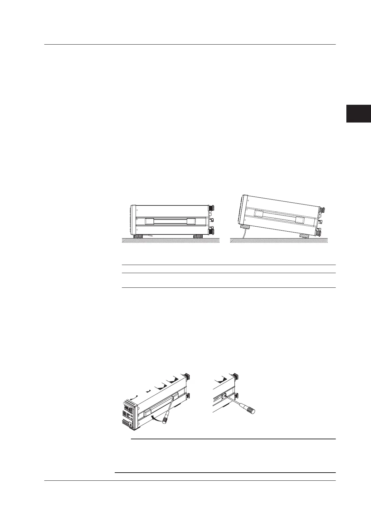
• Desktop
Place the instrument on a flat, even surface as shown in the figure below. If the
instrument is installed in a horizontal position, rubber stoppers can be attached to the
feet to prevent the instrument from sliding. Two sets (four pieces) of rubber feet are
included in the package.
• Rack Mount
To rack mount the instrument, use the rack mount kit that is sold separately.
Part Name Model Note
Rack mount kit 751535-E4 For EIA
Rack mount kit 751535-J4 For JIS
An outline of the attachment procedures is given below. For details regarding the
attachment procedures, see the instructions that are included with the rack mount kit.
1. Remove the handles from each side of the instrument.
2. Remove the four feet from the bottom of the instrument.
3. Remove the two plastic rivets and the four seals covering the rack mount
attachment holes on each side of the instrument near the front.
4. Places seals over the feet and handle attachment holes.
5. Attach the rack mount kit.
6. Mount the instrument on the rack.
Note
• When rack mounting the instrument, allow at least 20 mm of space around the inlet and vent
holes to prevent internal overheating.
• Make sure to provide adequate support from the bottom of the instrument. But, do not block
the inlet or vent holes in the process.
3.2 Installing the Instrument
 Loading...


