3-15
IM 760301-01E
3
Before Starting Measurements
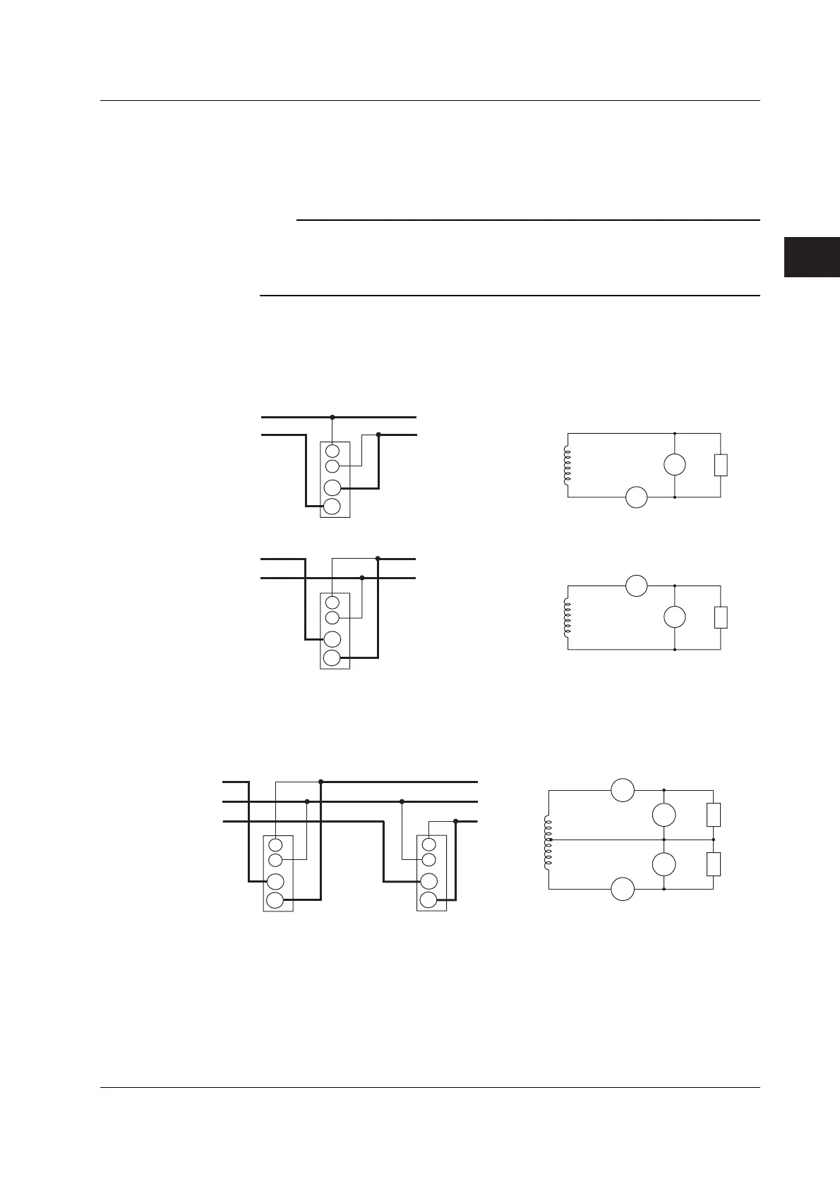
The assignment of elements to the input terminals in the figures of the wiring examples
below varies depending on the number of installed input elements. For details, see
“Number of Installed Input Elements and Wiring Systems” in section 2.3, “Measurement
Conditions.”
Note
• After wiring, the wiring system must be selected. See section 4.1, “Selecting the Wiring
System.”
• The thick lines on the wiring diagrams are the sections where the current flows. Use
appropriate wires that are suitable for the current.
Wiring Example of a Single-Phase, Two-Wire System (1P2W)
If four input elements are available, four single-phase, two-wire systems can be set up.
See section 3.7 for details on which wiring system below should to be selected.
SOURCE
LOAD
U1
I1
I
U
LOAD
U1
U
I1
I
SOURCE
SOURCE
LOAD
Input terminal
SOURCE
LOAD
Input terminal
±
±
±
±
I
±
U
±
I
±
U
±
Wiring Example of a Single-Phase, Three-Wire System (1P3W)
If four input elements are available, two single-phase, three-wire systems can be set up
(elements 1 and 2 and elements 3 and 4).
SOURCE
LOAD
N
N
SOURCE
Input terminal 1
LOAD
Input terminal 2
±
±
±
±
I
I
U
U
I2
I1
U1
U2
I
±
U
±
I
±
U
±
3.9 Wiring the Circuit under Measurement for Direct Input

 Loading...


