2-11
IM WT5000-02EN
2.3 Configuring the Current Sensor
Note
WhenrangeΣlink(seesection2.1)issettoon,theexternalcurrentsensorrangesoftheinputelements
assignedtothesamewiringunitaresettothesamerange.WhenrangeΣlinkissettooff,theexternal
current sensor ranges of the input elements can be set independently even when they are assigned to the
same wiring unit.
External Current Sensor Range and Conversion Ratio Configuration Example
When you measure a current with a maximum value of 100 A using a current sensor that produces 10 mV
when 1 A of current is flowing, the maximum voltage that the current sensor produces is 10 mV/A × 100 A = 1
V. Therefore, configure the settings as indicated below.
• External current sensor range: 1 V
• External current sensor conversion ratio: 10 mV/A
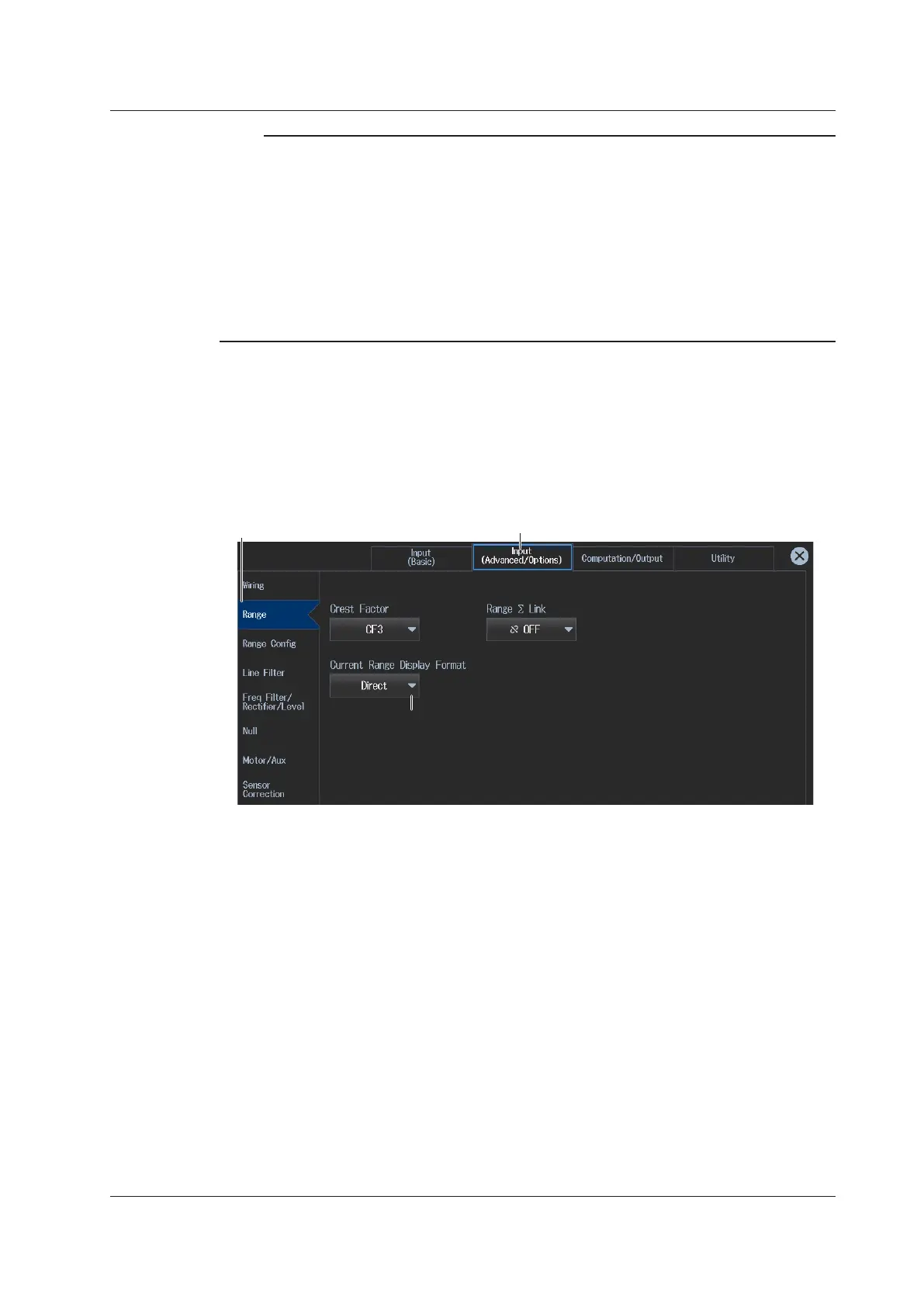
Setting the Current Range Display Format
(Current Range Display Format)
3.
Tap the Input (Advanced/Options) tab. An input settings (advanced/options) overview screen
appears.
Pressing ESC closes the overview screen.
4.
Tap Range. A setup screen appears for common measurement range items.
Input (Advanced/Options) tab
Range button
Set the current range display format (Direct, Measure).
 Loading...


