2-19
IM WT5000-02EN
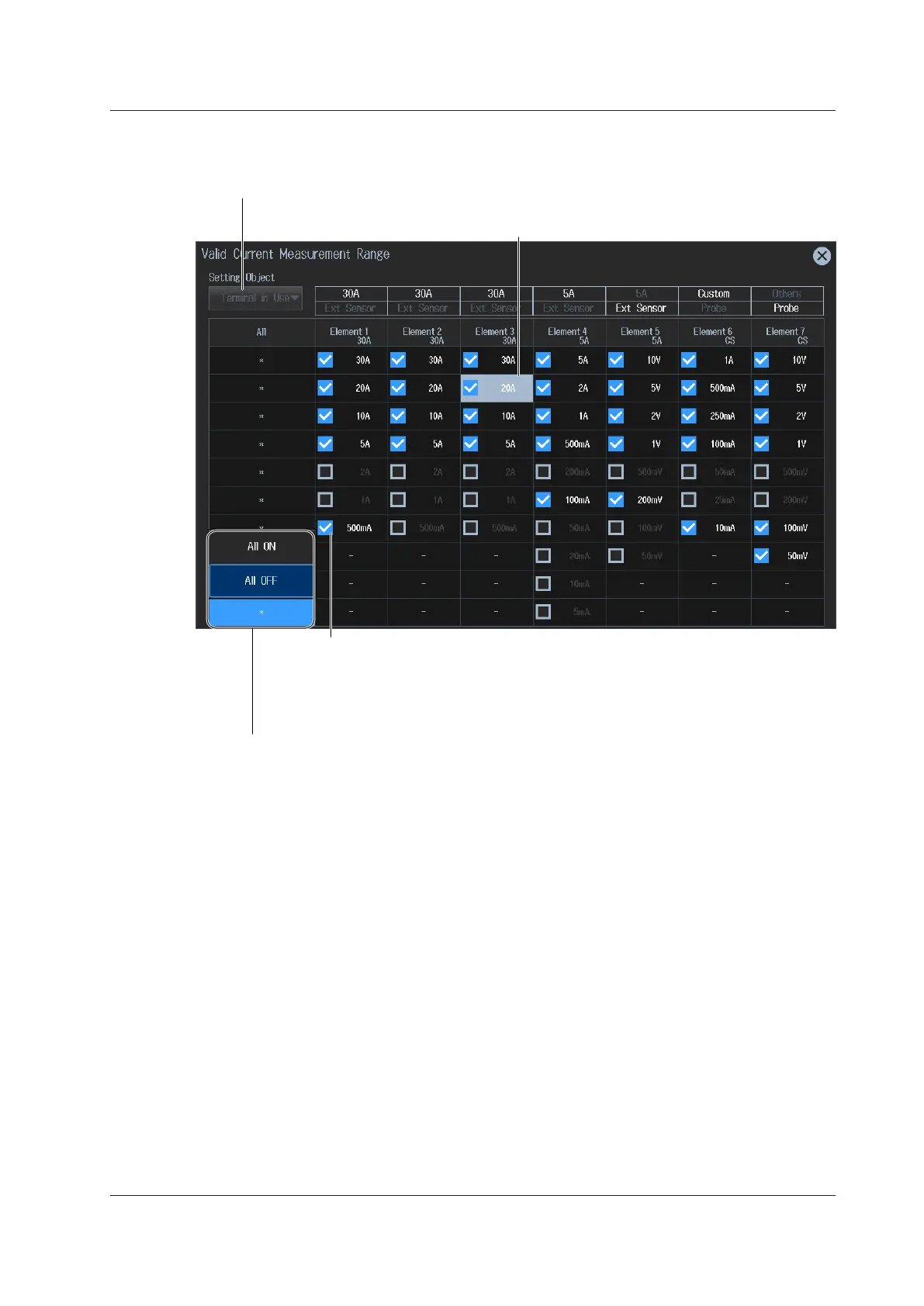
2.5 Setting the Valid Measurement Range
Setting Valid Measurement Ranges for Current (30 A input element example)
5.
Tap Valid Measurement Range. A valid current range setup screen appears.
If the measurement range to switch to when a peak over-range occurs
has been selected, the range background is displayed in gray.
Select the item to set the current range of (Terminal in Use, Direct/Sensor, Ext Sensor/Probe).
By tapping the asterisk of each range, you can collectively set or not set the applicable ranges
of all input elements or wiring units as valid measurement ranges (All ON or All OFF).
Valid measurement range
• The measurement range switches (in order) between the selected ranges.
• Ranges that are not selected are skipped.
• When Range Σ Link (see section 2.1) is set to ON, the input elements that
are assigned to the same wiring unit are set to the same status.
 Loading...


