SonTek/YSI
ADVField Software Manual (September 1, 2001) 11
2.4. Boundary Adjustment Mode
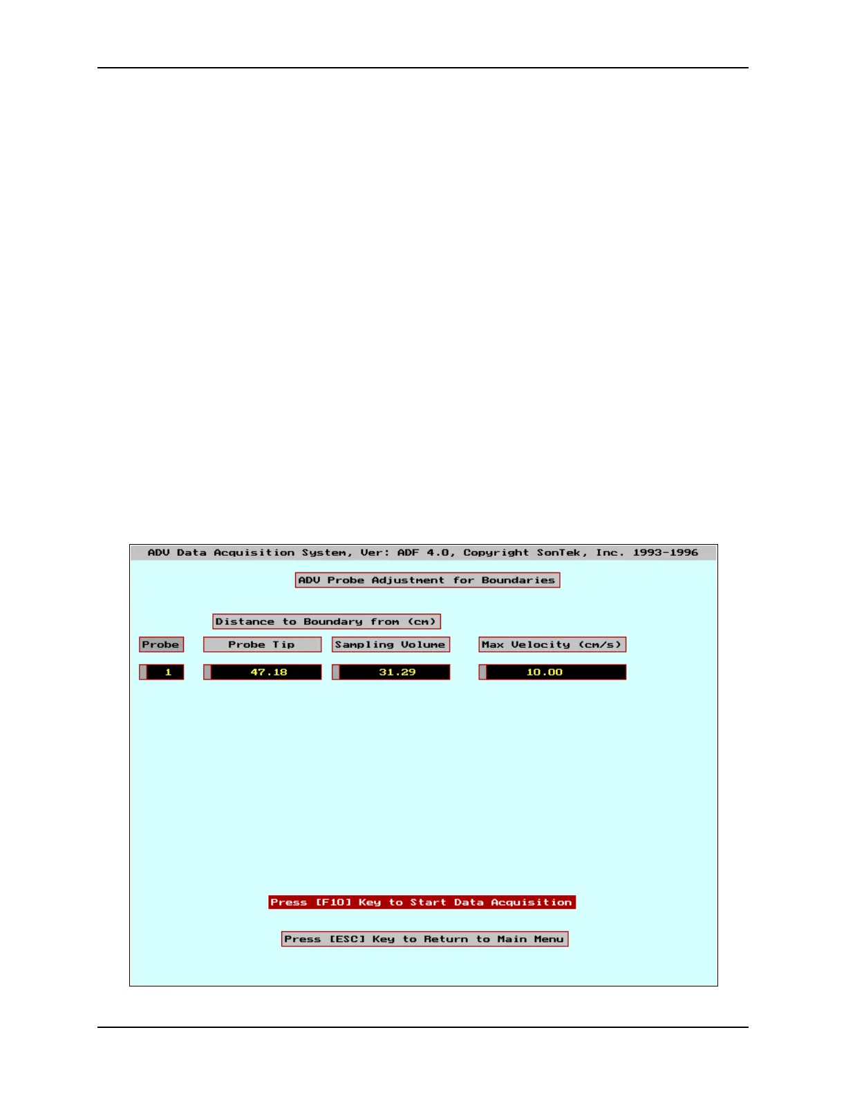
Figure 3 shows the boundary adjustment screen. In boundary adjustment mode, the ADV con-
tinuously scans the region in front of the probe to detect the presence of a solid or surface bound-
ary. The screen displays the probe number from the probe definition file (
ADVPROBE.DEF
), the
distance from the tip of the probe to the boundary, the distance from the center of the sampling
volume to that boundary, and the velocity range setting (see below). If no boundary is detected, it
displays
NOT DETECTED
.
The ADV can typically detect a boundary within 25 cm for the 16/10-MHz ADV or 50 cm for
the 5-MHz ADVOcean. Boundary information is useful for positioning the probe near the surface
or a solid boundary. The distance measurements are accurate to about ±1 mm for the 16/10-MHz
ADV and ±2 mm for the 5-MHz ADVOcean.
The boundary adjustment mode is necessary because the ADV must adjust its operation to pre-
vent boundary reflections from interfering with signals from the sampling volume. Under some
conditions, the presence of a boundary too close to the sampling volume may force the ADV to
reduce the user-selected velocity range. For this reason, the effective velocity range is also shown
on the screen. See the ADVField Principles of Operation for more information about boundaries
and the velocity range setting.
From this mode, you can proceed to the data acquisition mode by pressing <F10>, or go back to
the setup mode by pressing <Esc>. The program may take a few seconds to respond.
Figure 3 - Data Acquisition Software “Boundary Adjustment Mode”
 Loading...


