SonTek/YSI
ADVField/Hydra Operation Manual (September 1, 2001) 53
4.3. Input / Output Signals, Cables, and Connectors
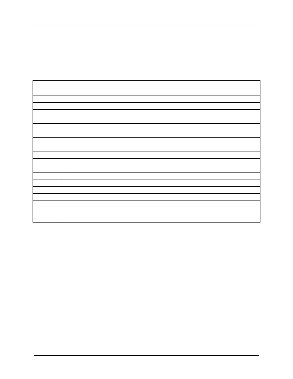
Table 15 summarizes the input and output signal lines used with the ADV. This also establishes
the naming convention used in the remainder of §4.3. Sections 4.3.1 and 4.3.2 describe how to
access these signals from the cables and connectors supplied with each type of ADV processing
module (ADVField splash proof housing and ADVField underwater canister).
Table 15. ADV Input/Output Signal Lines
Signal Description
Vx Analog output voltage proportional to Vx (or Veast) velocity component (§5.4)
Vy Analog output voltage proportional to Vy (or Vnorth) velocity component (§5.4)
Vz Analog output voltage proportional to Vz (or Vup) velocity component (§5.4)
Amp Analog output voltage proportional to the mean signal amplitude from the three
acoustic receivers
SyncOut Output synchronization signal generated by the ADV that is a short 5V pulse at the
end of each sample (§5.5)
SyncIn Input synchronization signal received by the ADV that triggers on the rising edge of
a 5V square wave (§5.5)
Ground The ADV uses a common ground for power and serial communication.
+5 V 5V power supply from the ADV processing module. This output has minimal drive
capability; a typical use is to trigger SyncIn (§5.5).
Vpower Input power to the ADV (12-24 VDC)
Data Out RS232 serial data output from ADV
Data In RS232 serial data input to ADV
Rx+ RS422 serial data input to ADV - positive wire (differential signal)
Rx- RS422 serial data input to ADV - negative wire (differential signal)
Tx+ RS422 serial data output from ADV - positive wire (differential signal)
Tx- RS422 serial data output from ADV - negative wire (differential signal)
4.3.1. ADVField Splash-Proof Housing
The front of the ADVField splash-proof housing (Figure 1) has four connectors, a power switch,
and a diode power light. The DB25 connector mates with the high-frequency cable from the
probe. The high-frequency cable is a custom shielded cable that is very sensitive to noise. Neither
the cable nor connector should be modified without contacting SonTek.
The coaxial power connector accepts 12-24 VDC power input. The connector has the positive
terminal on the inside and the negative terminal on the outside, matching the output of the supply
included with the ADV. The diode on the front panel will light if the system is powered up and
the power switch is ON. The toggle switch on the splash-proof housing allows the system to be
turned OFF and ON when power is connected.
The DB9 connector provides access to the serial communications lines of the ADV. This connec-
tor has been wired following standard serial communications protocol. When using RS232 com-
munications, a simple pin-to-pin cable can be used to connect the ADV to the DB9 serial port on
a PC-compatible computer (a ribbon cable is provided with the system for this purpose). Table
16 lists the pin-out for the DB9 connector.

 Loading...


