SonTek/YSI
Acoustic Doppler Velocimeter Principles of Operation (September 1, 2001)
2
Figure 1 shows the operation of a bistatic Doppler current meter, such as the ADV. The term
bistatic refers to the fact that the ADV uses separate acoustic transducers to transmit and to re-
ceive. Both transmitter and receiver are constructed to generate very narrow beam patterns. The
transmitter generates sound with the majority of the energy concentrated in a narrow cone, while
the receiver is most sensitive to sound coming from a very narrow angular range. The transducers
are mounted such that their beams intersect at a volume of water located some distance away.
This beam intersection determines the location of the sampling volume (the volume of water in
which measurements are made).
The transmitter generates a short pulse of sound at a known frequency, which propagates through
the water along the axis of its beam. As the pulse passes through the sampling volume, the acous-
tic energy is reflected in all directions by particulate matter (sediment, small organisms, bubbles,
etc.). Some portion of the reflected energy travels back along the receiver axis, where it is sam-
pled by the ADV and the processing electronics measure the change in frequency. The Doppler
shift measured by one receiver is proportional to the velocity of the particles along the bistatic
axis of the receiver and transmitter. The bistatic axis is located halfway between the axes of the
transmit and receive beams.
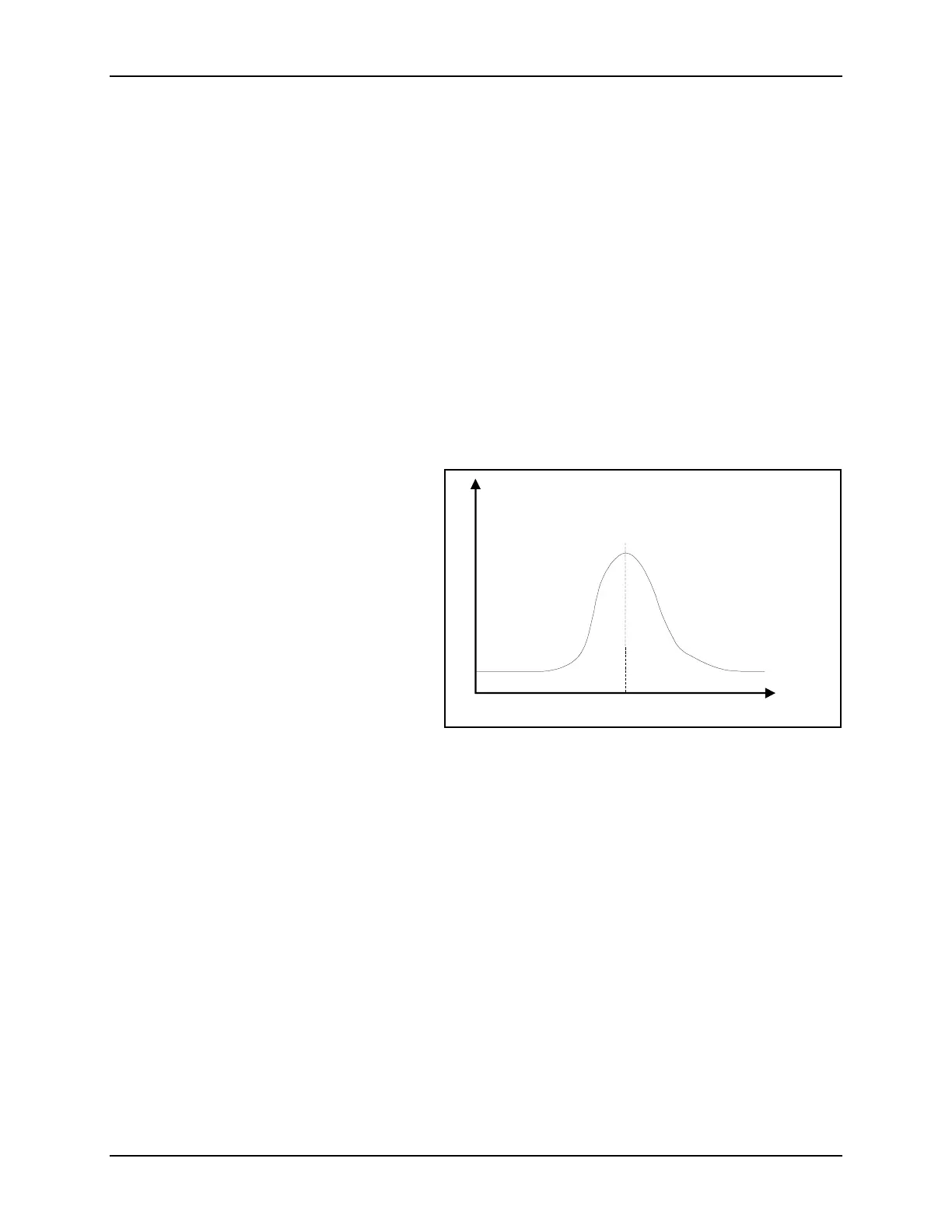
Figure 2 shows a typical profile of signal
strength versus time for one ADV re-
ceiver. The horizontal axis shows time af-
ter the transmit pulse, while the vertical
axis shows the return signal strength
measured by the receiver. As the transmit
pulse travels through the water, some por-
tion of the energy is reflected in all direc-
tions. Immediately following the transmit
pulse, the reflections that hit the receive
transducer come from an angle outside its
sensitive range; thus the receiver measures
only the ambient noise level. As the pulse
moves towards the sampling volume, the
return signal starts to come from a direction close to the receiver’s peak sensitivity; thus, the re-
ceiver sees an increase in signal strength. The signal strength reaches a maximum when the pulse
crosses the center of the receive beam; afterwards, the reflections move out of the receive beam
pattern and signal strength decays. The peak of the bell-shaped curve occurs when reflections are
coming from the intersection of transmit and receive beams. By sampling the return signal at this
time, the ADV makes measurements in the remote sampling volume defined by the intersection
of transmit and receive beams.
3. Beam Geometry and 3D Velocity Measurements
A single transmit/receive pair measures the projection of the water velocity onto its bistatic axis.
The ADV uses one transmitter and two or three acoustic receivers (for 2D or 3D probes). The re-
ceivers are aligned to intersect with the transmit beam pattern at a common sampling volume.
The ADV combines velocity measurements from each receiver, knowing the relative orientation
of the three bistatic axes, to calculate the 3D water velocity at the sampling volume.
Figure 2 – ADV Signal Strength Profile
Time after transmit pulse
Received signal strength
Center of
Receiver Axis
Ambient
oise Level

 Loading...


