SonTek/YSI
54
ADVField Operation Manual (September 1, 2001)
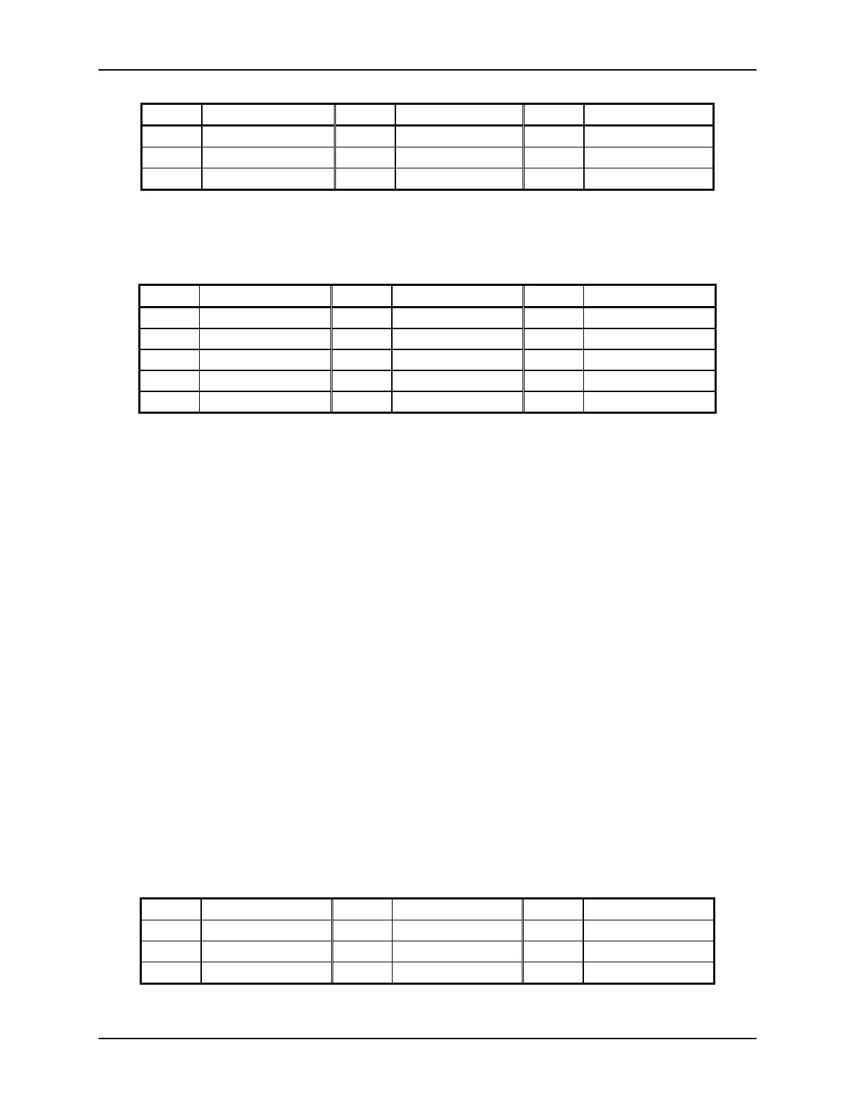
Table 16. DB9 Connector Pin-outs for Serial Communications
Pin # Signal Pin # Signal Pin # Signal
1 Rx- 4 Not used 7 Not used
2 Data Out / Tx+ 5 Ground 8 Not used
3 Data In / Tx- 6 Not used 9 Rx+
The last connector on the splash-proof housing, a DB15, gives access to auxiliary input / output
signals. Table 17 lists the pin out for the DB15 connector.
Table 17. DB15 Connector Pin-outs for Auxiliary I/O Signals
Pin # Signal Pin # Signal Pin # Signal
1 Vx 6 SyncIn 11 Ground
2 Vy 7 SyncOut 12 Ground
3 Vz 8 +5 V 13 Ground
4 Amp 9 Ground 14 Ground
5 Ground 10 Ground 15 Ground
4.3.2. ADVField Underwater Canister
There are two connectors on the ADVField underwater canister: one to the probe and the other
for power, serial communications, and auxiliary input / output functions. Underwater mateable
connectors are used for both (some older ADVs used different connectors; contact SonTek if you
have any questions about the connectors used on your system). The high-frequency cable from
the ADVField underwater canister to the probe is a custom-shielded, highly noise-sensitive cable.
Contact SonTek before making any modifications to this cable or connector.
SonTek uses underwater connectors made by Impulse Enterprises. Contact information for Im-
pulse (if ordering items directly) is:
Impulse Enterprises
8254 Ronson Road, San Diego, CA 92111
Phone (619) 565-7050, Fax (619) 565-1649
Two different types of connectors are used for power and communications.
• For most autonomous ADVField systems (with internal recorder and battery power):
o The external power and communication connector is a female, 8-pin, underwater mate-
able connector (although some use the female, 16-pin connector described below).
o The bulkhead connector used is an Impulse BH-8-FS.
o The mating connector on the cable is an Impulse IL-8-MP (with locking sleeve).
o Table 18 gives the pin-out for this connector.
Table 18. Impulse IL-8-MP Connector Pin-outs
Pin # Signal Pin # Signal Pin # Signal
1 Vpower 4 Drain 7 Rx-
2 Data Out / Tx+ 5 SyncIn 8 Ground
3 Data In / Tx- 6 Rx+

 Loading...


