SonTek/YSI
ADVField/Hydra Operation Manual (September 1, 2001) 51
4.2. ADVField Hardware Switches and Jumpers
The general layout of the ADVField processing module is given in §4.1. There are three places in
the processing module where hardware settings determine system configuration. Switches on the
Analog board select probe orientation and select the installed optional sensors. Two rotary dials
on the CPU board set the communications baud rate and the address for RS485 communication.
Finally, jumpers on the CPU board determine whether the ADV uses RS232, RS422, or RS485
serial communications protocol. See §4.4 for instructions on accessing the processing module.
Hardware Configuration Switches (Analog Board)
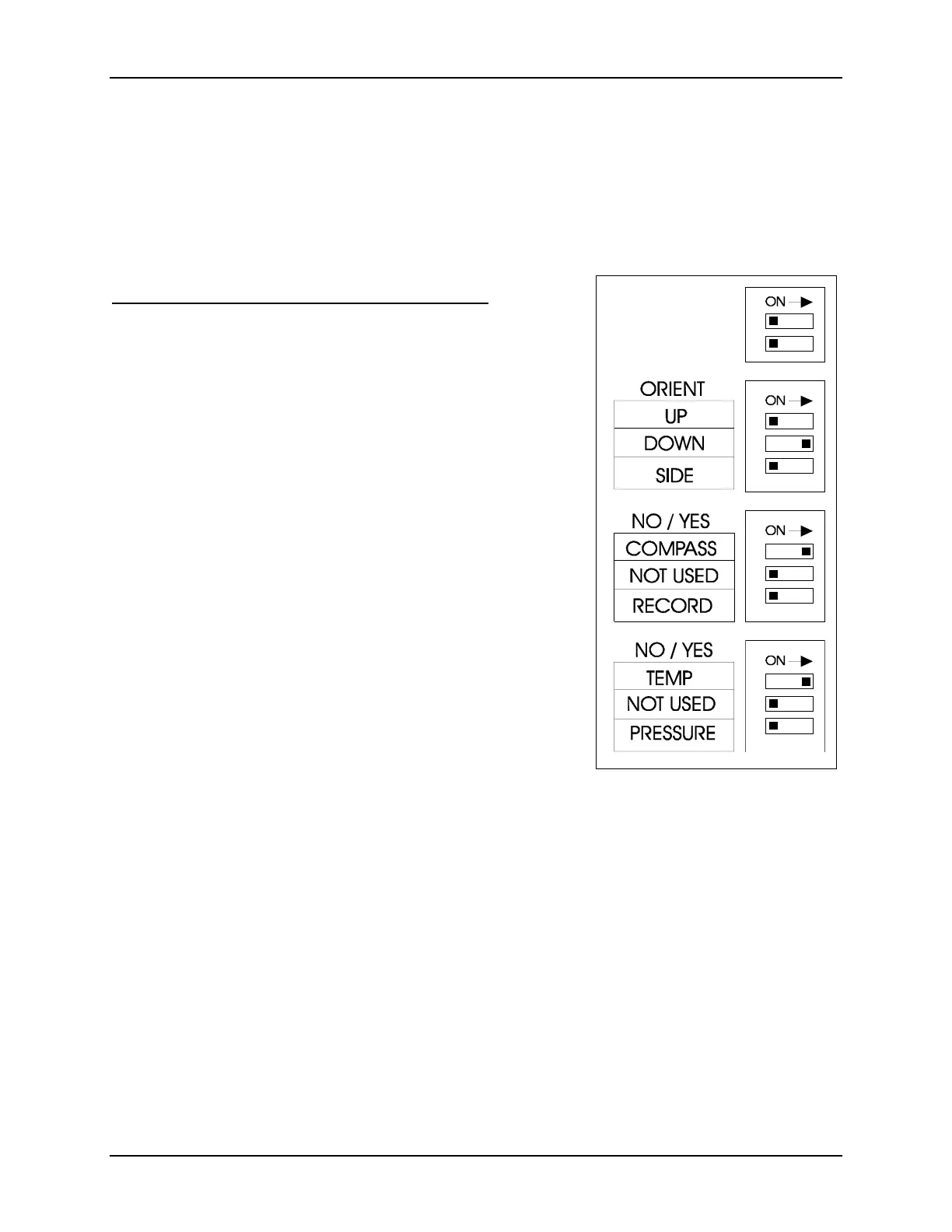
Figure 13 shows a diagram of the hardware configuration
switches on the Analog board. The switches are divided into
one set of two, and three sets of three. The top set (of two) is
not used by the ADVField. Placing any switch to the right (as
shown in Figure 13) is ON and to the left is OFF.
The first set of three switches defines the orientation of the
compass with respect to the ADV probe. These switches are
only used if the optional compass is installed. If the compass is
not installed, the ADV will always show an orientation of
DOWN, and velocity data will be reported in the XYZ coordi-
nate system relative to the probe orientation (see §5.1). Only
one of the orientation switches should be ON at any time.
Switch #1 indicates the system is deployed looking up, switch
#2 indicates the system is looking down, and switch #3 indi-
cates the system is deployed looking to the side.
Note: When switching to up, down, or side-looking, you must
set the correct switch and change the physical mounting of the
compass. See §4.7.2 for details on changing compass orienta-
tion and to ensure that the physical orientation of the compass,
the orientation switch setting, and the probe deployment orien-
tation are the same.
The second set of switches defines which optional sensors
have been installed. If switch #1 is ON, the system will look for the internal compass and tilt sen-
sor. If the ADV cannot detect this sensor, it will return an error message when entering the
Command Mode. Switch #2 is not used. Switch #3 indicates whether the internal recorder is in-
stalled. This switch must be set to ON to use the internal recorder.
The last set of switches specifies which peripheral sensors are installed. Switch #1 should be ON
if the ADV includes the optional temperature sensor. Switch #2 is not used. Switch #3 should be
ON if the ADV includes the optional pressure sensor.
All switches are set to the appropriate value at the factory. The only settings that would normally
be changed by the user are the orientation switches. The switch settings shown in Figure 13 indi-
cate a down-looking ADV with the optional compass and temperature sensors installed (no re-
corder or pressure sensor).
Figure 13 - ADVField Analog
Board Switches

 Loading...


