SonTek/YSI
ADVField/Hydra Operation Manual (September 1, 2001) 47
Section 4. ADVField System Hardware
4.1. ADVField Processing Module Overview
Figure 8 shows the general layout of the ADVField processing module. The processing module
consists of three printed circuit (PC) boards with an optional fourth board for internal recording.
The boards are connected in a vertical stack using multiple conductor connectors at one or both
ends of the boards. The top-down
board order is: Analog, DSP, CPU,
and Recorder. Each board is la-
beled in white letters. The board
dimensions are 10.1 x 15.2 cm (4
x 6 in) and are separated vertically
by 1.3 cm (0.5 in). A general de-
scription of the function and layout
of each board follows.
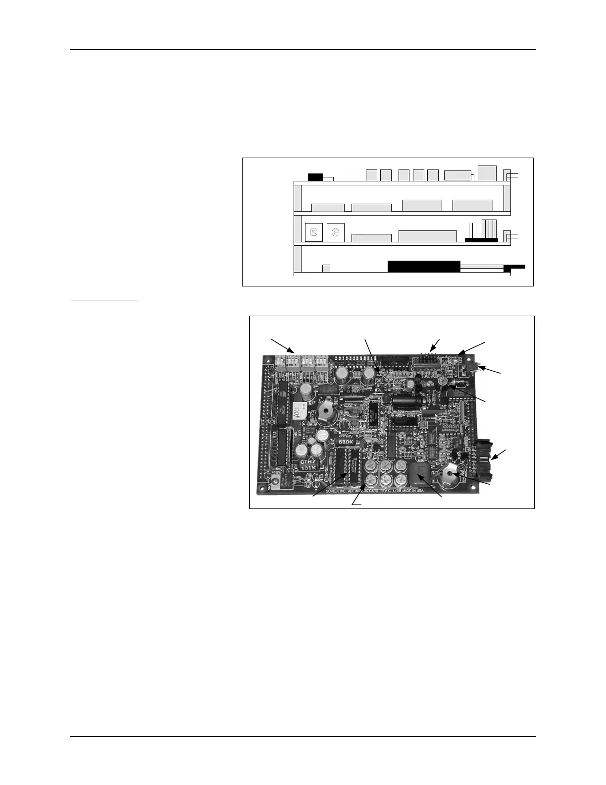
Analog Board
Figure 9 shows the layout of the
Analog board with a few important
features labeled. The Analog board
generates the acoustic transmit sig-
nals, receives the high-frequency re-
turn signals, and does preliminary
signal conditioning before the return
signal is sent to the DSP. Important
features of the Analog board include:
• Hardware Configuration Switches
– These switches are used to set
the orientation of the probe and to
select the installed optional sen-
sors (compass, recorder, tempera-
ture, pressure). See §4.2 for de-
tails on setting these switches.
• CPU Backup Battery Connector – This keyed, 2-pin, red connector is wired to a backup bat-
tery for systems with the internal recorder; it is not used in real-time systems. (Note: This is
the same connector as for the front end-plate diode on the ADVField splash-proof housing; the
backup battery cannot be installed in the splash-proof housing.)
• Temp/Pressure Connector – This 10-pin, black connector receives signals from the optional
temperature and pressure sensors. This connector is not keyed, so note its orientation before
removal. The cable from this connector goes to the probe.
• Power Diode / Connector – This diode will light if the ADV electronics has at least 12V input
power. For the ADVField splash-proof housing, this diode is replaced with a red, 2-pin con-
nector leading to a diode on the front end-plate. This is the same connector as for the backup
battery, but not the same connector used for input power.
Analog
DSP
CPU
Recorder
0
0
Fi
ure 8 - ADVField Processin
Module
Figure 9 - ADVField Analog Board
Hardware con-
fi
u
ation switches
CPU backup
batter
connecto
Temp/Pressure
Power diode
(U/W sys-
tems only)
Input power
Input powe
fuse
Probe
connecto
Transmit
transforme
Transmit capacitor
Transmit FETs
Transmit driver

 Loading...


