SonTek/YSI
48
ADVField Operation Manual (September 1, 2001)
• Input Power Connector – This keyed, 2-pin, red connector accepts DC input power (12-24 V).
The polarity for each pin is labeled. The cable from this connector will lead either to the input
power connector (ADVField in splash-proof housing) or to the power and communications
underwater connector (ADVField in underwater canister).
• Input Power Fuse – This black, cylindrical, plug-in fuse is rated at 3.15A, 250V. To test the
fuse, remove it from its socket and test for continuity between the pins. Spare fuses are in-
cluded in the ADV tool kit. A blown fuse most often indicates a problem with the power sup-
ply or that interference is causing a short in the ADV processing module.
• Probe Connector – This keyed, 16-pin, black rectangular connector carries high-frequency
analog signals to/from the probe. These signals are highly sensitive to noise; do not modify the
cables or connectors without first contacting SonTek. The cable from this connector goes to
the probe. (Note: The connector used is the same as one of the connectors on the DSP board.)
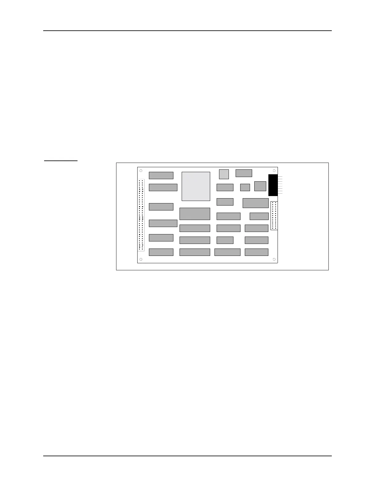
DSP Board
Figure 10 shows the
layout of the DSP
board with a few im-
portant features la-
beled. The DSP digi-
tizes the return signal
and performs Doppler
calculations to deter-
mine velocity. The im-
portant features of the
DSP board include:
• DSP – The digital
signal processor
chip provides the major computational power of the ADV electronics.
• DSP EPROM – This chip stores the digital processing algorithms used by the ADV to meas-
ure velocity. Upgrades for this EPROM may be available periodically. See §4.4.7 for replace-
ment instructions.
• Aux. I/O Connector – This keyed, 16-pin, black rectangular connector carries the analog out-
put voltages and synchronization signals (SyncIn and SyncOut; see §5.4 and §5.5 for details).
The cable from this connector goes to the DB15 auxiliary input/output connector (ADVField
in splash-proof housing) or to the power/communications connector (ADVField in underwater
canister). (Note: This connector is the same as one of the connectors on the Analog board.)
• Half-Length Card Connector – This 26-pin connector mates to a connector on the bottom of
the Analog board.
• Full-Length Card Connector – This 64-pin connector mates to a connector on the bottom of
the Analog board and to a connector on the CPU board.
Aux. I/O
Connector
SONTEK INC. ADF DSP CARD REV. D 12
95 MADE IN USA
DSP
DSP
EPROM
Half Length
Card Connector
F
u
L
e
n
g
t
C
a
r
d
C
o
n
n
e
c
t
o
r
Figure 10 - ADVField DSP Board

 Loading...


